
 EN
Selecting the right IGCT module specifications is fundamental to ensuring your industrial power conversion project achieves its performance targets and operational reliability. IGCT module specifications define the electrical limits, thermal behavior, and mechanical fit of insulated gate commutated thyristor modules, and misaligning these specifications with your actual project demands creates cascading risks throughout your system design and deployment lifecycle. Engineers and procurement teams must understand how voltage ratings, current capacity, switching frequency capabilities, and thermal characteristics of IGCT module specifications interact with application-specific requirements before finalizing component selection.
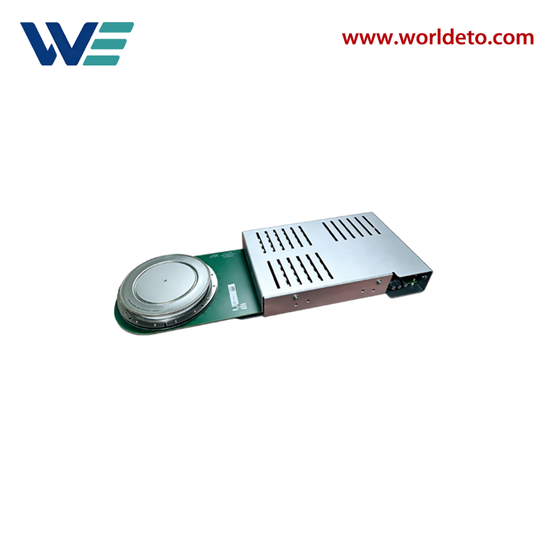
The process of matching IGCT module specifications to project needs extends beyond simple datasheet cross-referencing. It requires systematic evaluation of peak and continuous operating conditions, ambient temperature constraints, cooling infrastructure availability, circuit topology requirements, and long-term reliability expectations. Failure to properly align IGCT module specifications with your design environment leads to undersizing that risks thermal runaway, oversizing that increases cost without benefit, or specification mismatches that prevent proper gate driver integration and control system compatibility.
Understanding Core IGCT Module Specifications
Voltage and Current Ratings in IGCT Module Specifications
Every IGCT module specifications sheet lists voltage ratings that define the maximum peak repetitive voltage the device can safely block. Standard IGCT module specifications typically range from 1700V to 6500V in power conversion applications, with each voltage class requiring distinct component architectures and thermal management approaches. Current ratings within IGCT module specifications indicate both continuous DC current capability and peak pulse current limits, with continuous ratings determining steady-state thermal behavior and pulse ratings defining dynamic overload performance.
Matching voltage in IGCT module specifications to your circuit requires understanding both nominal bus voltage and transient overvoltage margins. A well-designed system typically selects IGCT module specifications with voltage ratings approximately 20 to 40 percent higher than maximum expected circuit voltage to accommodate switching transients, utility voltage fluctuations, and temporary fault conditions. Current selection in IGCT module specifications demands similar margin analysis, balancing continuous load current, periodic peak demands, and emergency overload intervals against the thermal capacity and cooling efficiency your installation can provide.
Switching Frequency and Loss Profile in IGCT Module Specifications
IGCT module specifications define switching frequency capabilities through turn-on and turn-off characteristics that directly influence conduction losses and switching losses. High-frequency operation favors IGCT module specifications designed for reduced gate charge and faster commutation, while lower frequency applications benefit from IGCT module specifications optimized for minimal on-state voltage drop. The loss profile embedded in IGCT module specifications determines cooling requirements and overall system efficiency, making this specification category critical to matching performance expectations with realistic thermal and power budget realities.
Aligning IGCT Module Specifications With Application Environment
Thermal Management and Cooling Compatibility
Thermal characteristics within IGCT module specifications reveal how the device dissipates power and manages heat under operating stress. Junction-to-case thermal resistance (Rjc) and case-to-ambient thermal resistance (Rca) values in IGCT module specifications determine what heatsink size, fin design, and coolant flow rate your installation must provide to maintain safe junction temperatures. Selecting IGCT module specifications without confirming your cooling infrastructure can sustain the required heat removal creates a fundamental design mismatch that limits actual device performance regardless of datasheet ratings.
IGCT module specifications must account for your ambient temperature environment, cooling medium availability, and heatsink mounting constraints. Industrial applications operating in confined enclosures with limited airflow require IGCT module specifications from lower power tiers or devices optimized for natural convection cooling. Conversely, outdoor installations with robust liquid cooling systems can utilize higher-power IGCT module specifications that demand aggressive thermal management. Your cooling architecture must directly inform which IGCT module specifications are practically viable for your project.
Gate Driver and Control System Integration
IGCT module specifications include gate charge (Qg), gate voltage requirements, and minimum dv/dt values that determine gate driver circuit design and control system compatibility. Mismatching IGCT module specifications with inadequate gate driver performance creates slow switching transitions, excessive losses, and unreliable device commutation. Each IGCT module specifications variant requires specific gate driver specifications for stable operation, and selecting IGCT module specifications without confirming gate driver availability forces costly redesigns late in your project timeline.
Control architecture integration with IGCT module specifications extends to signal propagation delays, dead-time requirements between complementary switches, and protection circuit coordination. Modern IGCT module specifications incorporate integrated gate units (IGUs) that simplify driver integration, while traditional IGCT module specifications require discrete external gate drivers with precise timing coordination. Understanding which IGCT module specifications variants your control platform can reliably support prevents late-stage integration failures and ensures consistent performance across your installation lifecycle.
Verification and Long-Term Performance Alignment
Datasheet Review and Specification Margin Analysis
Systematic datasheet review of IGCT module specifications begins with voltage and current ratings, then extends to thermal parameters, switching characteristics, and protective capabilities. Each IGCT module specifications document lists absolute maximum ratings, recommended operating regions, and safe operating areas (SOA) that define where the device performs reliably versus where failure risk accelerates. Matching your application within the recommended region of IGCT module specifications rather than approaching absolute limits ensures predictable performance and extended device lifespan throughout your project deployment phase and subsequent operational years.
IGCT module specifications analysis should include worst-case scenario evaluation across temperature extremes, component aging, and manufacturing tolerance variations. Selecting IGCT module specifications with 50 percent margin above nominal design requirements accommodates component degradation, environmental stress, and unexpected load growth without forcing emergency redesigns. This conservative approach to IGCT module specifications selection protects your capital investment and operational continuity while minimizing unplanned maintenance and unexpected downtime across your industrial power systems.
Reliability Testing and Field Performance Validation
Before full-scale deployment, prototype testing of selected IGCT module specifications under representative operating conditions confirms theoretical performance matches real-world behavior. Temperature cycling, load transient injection, and thermal stress testing of IGCT module specifications reveal whether your cooling infrastructure, gate driver timing, and protection circuits function as designed. Field pilot programs with matched IGCT module specifications installations provide valuable operational data that informs whether your specification selection process requires adjustment for future similar projects.
Long-term field experience with deployed IGCT module specifications installations provides essential feedback for refining specification matching processes and identifying potential environmental or operational factors that influence device reliability. Documenting thermal behavior, switching efficiency, and failure modes of IGCT module specifications across diverse installations creates institutional knowledge that strengthens your engineering team's capability to select optimal IGCT module specifications for increasingly complex applications. This continuous learning cycle transforms specification matching from a static datasheet exercise into a dynamic, experience-informed engineering discipline.
FAQ
What are the most critical IGCT module specifications to verify first?
Begin with voltage and current ratings of IGCT module specifications, confirm thermal resistance values align with your cooling capacity, then verify gate driver compatibility and switching frequency suitability. These four IGCT module specifications categories capture the primary failure modes when specifications misalign with project requirements.
How much specification margin should I include when selecting IGCT module specifications?
IGCT module specifications selection should include 20 to 40 percent voltage margin above maximum circuit voltage and similar current margin above sustained load requirements. This conservative IGCT module specifications approach accommodates transients, component aging, and environmental variation without sacrificing cost-effectiveness or forcing frequent redesigns.
Can I substitute different IGCT module specifications from different manufacturers in the same application?
IGCT module specifications vary significantly between manufacturers even at identical voltage and current ratings, with differences in switching characteristics, thermal behavior, and gate driver requirements. Substituting different IGCT module specifications requires complete re-validation of gate driver timing, thermal management, and protection circuit coordination before field deployment.