
 EN
EN
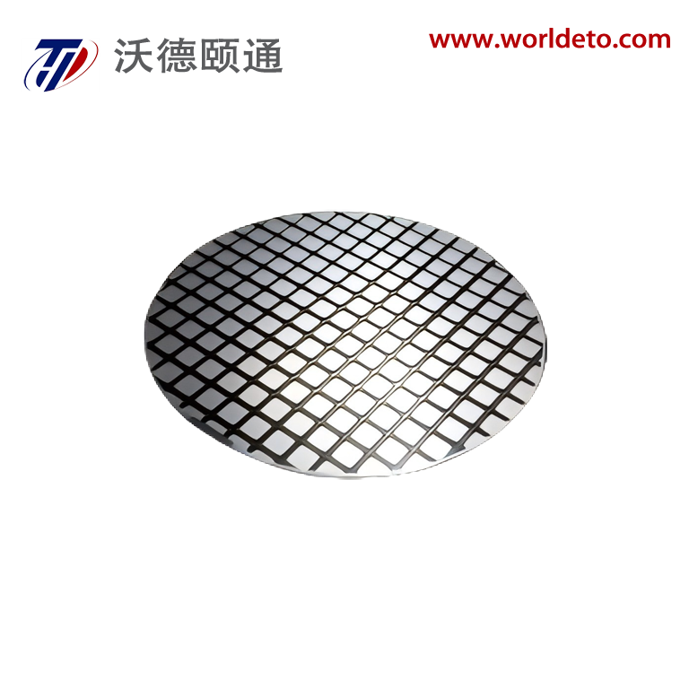
The field-stop layer is one of the most consequential structural elements in modern power semiconductor design, and understanding its profile is central to advancing the performance of any IGBT Wafer intended for high-voltage, high-current applications. As power electronics continue to push into more demanding operating environments — from traction drives to grid-level converters — the precision with which the field-stop layer is engineered directly determines switching speed, leakage behavior, and thermal robustness. Engineers and procurement specialists working with advanced IGBT Wafer technology must therefore develop a clear understanding of how field-stop profiles are characterized, optimized, and validated across different wafer generations.
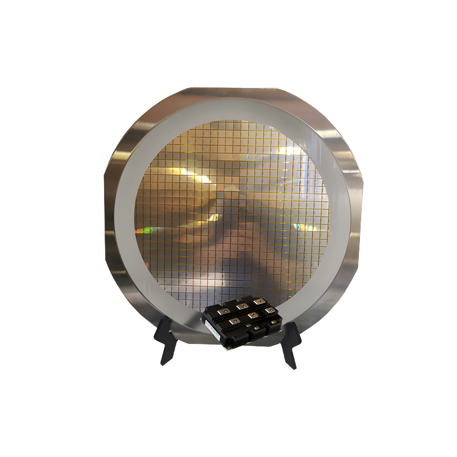
This article examines the structural logic behind field-stop layer profiles in advanced IGBT Wafer technology, exploring how doping gradients, layer thickness, and carrier lifetime engineering interact to shape device behavior. Whether you are evaluating wafer specifications for a new design or seeking to understand why certain IGBT Wafer configurations outperform others in soft-switching topologies, the analysis here provides the technical depth and practical context needed to make informed decisions.
The Role of the Field-Stop Layer in IGBT Wafer Architecture
Structural Position and Functional Purpose
In a conventional punch-through IGBT Wafer, the depletion region during forward blocking extends fully through the n-base and reaches the p-collector, which creates significant trade-offs in terms of on-state voltage drop and switching losses. The field-stop concept was introduced to address this limitation by inserting a moderately doped n-type buffer layer between the lightly doped n-base and the p-collector emitter. This layer arrests the electric field before it reaches the collector, allowing the designer to use a thinner n-base without sacrificing voltage blocking capability.
The practical consequence for IGBT Wafer design is substantial. A thinner n-base reduces the total stored charge during conduction, which directly lowers turn-off switching losses. At the same time, the field-stop layer must be carefully profiled so that it does not introduce abrupt doping transitions that could cause snap-off during turn-off — a condition where the tail current collapses too rapidly and generates destructive voltage spikes. The balance between these competing requirements defines the engineering challenge at the heart of field-stop layer optimization.
Modern IGBT Wafer platforms targeting 1200V to 6500V blocking classes all rely on field-stop architectures, but the specific profile of the field-stop layer varies considerably depending on the intended application, the wafer thickness, and the carrier lifetime management strategy employed during fabrication.
Doping Profile Characteristics and Their Electrical Implications
The doping concentration within the field-stop layer of an IGBT Wafer is not uniform. A well-engineered field-stop profile typically exhibits a graded or Gaussian distribution rather than a sharp box profile. This gradual transition from the field-stop peak concentration back toward the lightly doped n-base is critical for controlling the shape of the electric field during blocking and the dynamics of carrier extraction during turn-off.
When the field-stop doping profile is too abrupt on the collector side, the electric field develops a secondary peak at the field-stop boundary, which can accelerate impact ionization and reduce the safe operating area of the IGBT Wafer. Conversely, if the field-stop concentration is too low or the layer is too thin, the depletion region may punch through into the collector under high-voltage transients, defeating the purpose of the field-stop architecture entirely.
Simulation tools such as TCAD are routinely used during IGBT Wafer development to model the electric field distribution across the field-stop layer under various bias conditions. These simulations allow engineers to iterate on implant dose, energy, and anneal conditions before committing to a full wafer fabrication run, significantly reducing development cycle time and material cost.
Fabrication Methods That Shape Field-Stop Layer Profiles
Proton Irradiation and Hydrogen-Induced Donors
One of the most widely adopted techniques for forming the field-stop layer in an IGBT Wafer is proton irradiation followed by annealing. When protons are implanted into a float-zone or Czochralski silicon substrate at a precisely controlled energy, they come to rest at a depth determined by the Bragg peak of the implant. Subsequent annealing at temperatures typically between 350°C and 450°C converts the implant damage into hydrogen-related donor complexes, creating a localized n-type doping region that forms the field-stop layer.
The advantage of proton irradiation for IGBT Wafer fabrication is the ability to place the field-stop layer at a very precise depth without requiring high-temperature diffusion steps that could disturb the front-side device structures. Multiple proton implants at different energies can be used to create a broader or more complex field-stop profile, giving process engineers considerable flexibility in tailoring the doping distribution to meet specific electrical targets.
However, proton irradiation also introduces recombination centers throughout the wafer, which affects carrier lifetime in the n-base. Managing this side effect is an important aspect of IGBT Wafer process integration, as excessive lifetime reduction increases on-state voltage drop while insufficient lifetime control leads to slow turn-off and high switching losses.
Epitaxial Growth and Ion Implantation Approaches
An alternative approach to field-stop layer formation in IGBT Wafer technology involves epitaxial deposition of a doped silicon layer on the back side of a thinned wafer. This method offers excellent control over layer thickness and doping uniformity, but it requires wafer thinning to be completed before the epitaxial step, which introduces handling challenges for large-diameter substrates.
Ion implantation of phosphorus or arsenic through the back side of a thinned IGBT Wafer is another established technique. The implant is followed by a laser anneal or rapid thermal anneal to activate the dopants without exposing the front-side metallization to damaging temperatures. Laser annealing in particular has become a preferred method in advanced IGBT Wafer production lines because it confines the thermal budget to a very shallow surface region, preserving the integrity of the field-stop profile and the collector emitter structure simultaneously.
Each fabrication approach produces a field-stop layer with a distinct doping profile shape, and the choice of method has downstream consequences for the electrical characteristics of the finished IGBT Wafer. Process engineers must therefore align the fabrication method with the target application requirements from the earliest stages of device design.
Analyzing Field-Stop Profiles Through Characterization Techniques
Spreading Resistance Profiling and Secondary Ion Mass Spectrometry
Characterizing the actual doping profile of the field-stop layer in a fabricated IGBT Wafer requires techniques capable of resolving concentration variations over depth ranges of several micrometers with high spatial resolution. Spreading resistance profiling, or SRP, is one of the most direct methods available. It involves beveling the wafer cross-section at a shallow angle and measuring the local resistivity at closely spaced intervals along the bevel, from which the doping concentration profile is reconstructed.
SRP provides a continuous profile from the wafer surface through the field-stop layer and into the n-base, making it possible to verify that the field-stop peak concentration, layer width, and transition gradients all fall within the design specification. Deviations from the target profile can be traced back to process variations in implant dose, anneal temperature, or wafer thickness uniformity, enabling rapid root-cause analysis during process development for the IGBT Wafer.
Secondary ion mass spectrometry, or SIMS, complements SRP by providing elemental concentration data with high sensitivity, particularly useful for detecting hydrogen-related donor species in proton-irradiated IGBT Wafer structures. SIMS can resolve the depth distribution of implanted species with sub-nanometer precision, making it indispensable for validating the placement accuracy of field-stop layers formed by proton irradiation or ion implantation.
Electrical Characterization and Correlation to Profile Data
Physical profile data from SRP and SIMS must ultimately be correlated with electrical measurements to confirm that the field-stop layer is performing as intended in the finished IGBT Wafer. Key electrical parameters that reflect field-stop layer quality include the collector-emitter breakdown voltage, the leakage current at rated blocking voltage, and the shape of the turn-off current tail.
A well-profiled field-stop layer produces a smooth, controlled current tail during turn-off, indicating that stored charge is being extracted gradually without snap-off. If the tail current exhibits an abrupt collapse, it suggests that the field-stop layer is either too thin or too heavily doped, causing the depletion region to reach the collector prematurely and cutting off hole injection before the stored charge is fully removed. This behavior is particularly problematic in IGBT Wafer devices used in resonant or soft-switching converter topologies where controlled tail current behavior is essential for circuit operation.
Combining physical and electrical characterization data creates a feedback loop that allows process engineers to refine the field-stop profile iteratively, converging on a design that meets all performance targets across the full operating range of the IGBT Wafer.
Field-Stop Profile Optimization for Specific Application Classes
High-Frequency Inverter Applications
In high-frequency inverter applications such as motor drives operating above 10 kHz, the switching losses of the IGBT Wafer dominate the total power dissipation budget. For these applications, the field-stop layer profile must be optimized to minimize stored charge in the n-base while maintaining adequate voltage blocking capability. This typically means using a thinner n-base with a relatively narrow field-stop layer positioned close to the collector, combined with aggressive carrier lifetime reduction in the n-base to accelerate charge extraction during turn-off.
The trade-off is an increase in on-state voltage drop, which must be managed through careful optimization of the collector emitter structure and the gate oxide parameters. For the IGBT Wafer designer, the field-stop profile in this application class is characterized by a sharper doping gradient on the n-base side and a more gradual transition on the collector side, producing a profile that supports fast but controlled turn-off without snap-off.
Thermal management also becomes more critical at high switching frequencies, and the field-stop layer profile indirectly influences thermal performance by affecting the distribution of power dissipation within the IGBT Wafer cross-section. A well-optimized profile concentrates heat generation closer to the surface where it can be more efficiently extracted through the module package.
High-Voltage Traction and Grid Applications
At the opposite end of the application spectrum, IGBT Wafer devices used in traction converters and high-voltage direct current transmission systems operate at switching frequencies below 1 kHz and must sustain blocking voltages of 3300V, 4500V, or 6500V. In these applications, the field-stop layer profile must support a much thicker n-base, and the priority shifts from minimizing switching losses to maximizing ruggedness and short-circuit withstand capability.
The field-stop layer in a high-voltage IGBT Wafer for traction applications is typically broader and more gradually doped than its counterpart in a high-frequency device. This broader profile provides a larger margin against punch-through under transient overvoltage conditions and supports a softer, more controlled turn-off tail that reduces the risk of voltage overshoot in the converter circuit.
Process engineers developing IGBT Wafer technology for these voltage classes must also account for the interaction between the field-stop layer and the carrier lifetime profile established by electron irradiation or platinum diffusion. The combined effect of these two process steps determines the overall charge dynamics of the device and must be co-optimized to achieve the target balance between conduction loss and switching loss at the rated operating point.
FAQ
What is the primary function of the field-stop layer in an IGBT Wafer?
The field-stop layer in an IGBT Wafer serves to arrest the depletion region before it reaches the p-collector during forward blocking. This allows the n-base to be made thinner than in a conventional punch-through design, reducing stored charge and switching losses while maintaining the required voltage blocking capability. The profile of the field-stop layer — its doping concentration, thickness, and gradient — directly determines how effectively it performs this function across the full range of operating conditions.
How does the field-stop layer profile affect turn-off behavior in an IGBT Wafer?
The shape of the field-stop doping profile has a direct influence on the turn-off current tail of the IGBT Wafer. A gradual, well-graded profile on the n-base side of the field-stop layer allows the depletion region to expand smoothly during turn-off, producing a controlled tail current that decays without snap-off. An abrupt or overly concentrated field-stop profile can cause the tail current to collapse suddenly, generating voltage spikes that stress the device and the surrounding circuit components.
Which fabrication techniques are most commonly used to form the field-stop layer in advanced IGBT Wafer production?
The most widely used techniques for field-stop layer formation in advanced IGBT Wafer production are proton irradiation with low-temperature annealing, back-side ion implantation of phosphorus followed by laser annealing, and epitaxial deposition on thinned substrates. Each method produces a distinct doping profile shape and has different implications for process integration, wafer handling, and the interaction with carrier lifetime management steps. The choice of technique depends on the target voltage class, the required profile precision, and the constraints of the overall fabrication flow.
How are field-stop layer profiles verified in a finished IGBT Wafer?
Field-stop layer profiles in a finished IGBT Wafer are typically verified using a combination of spreading resistance profiling and secondary ion mass spectrometry to obtain physical doping concentration data as a function of depth. These physical measurements are then correlated with electrical characterization data, including breakdown voltage, leakage current, and turn-off waveform analysis, to confirm that the field-stop layer is performing according to the design specification. Discrepancies between the target and measured profiles are used to guide process adjustments in subsequent fabrication runs.
Table of Contents
- The Role of the Field-Stop Layer in IGBT Wafer Architecture
- Fabrication Methods That Shape Field-Stop Layer Profiles
- Analyzing Field-Stop Profiles Through Characterization Techniques
- Field-Stop Profile Optimization for Specific Application Classes
-
FAQ
- What is the primary function of the field-stop layer in an IGBT Wafer?
- How does the field-stop layer profile affect turn-off behavior in an IGBT Wafer?
- Which fabrication techniques are most commonly used to form the field-stop layer in advanced IGBT Wafer production?
- How are field-stop layer profiles verified in a finished IGBT Wafer?