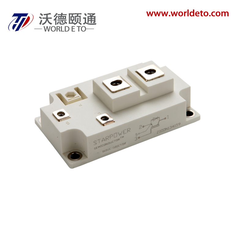
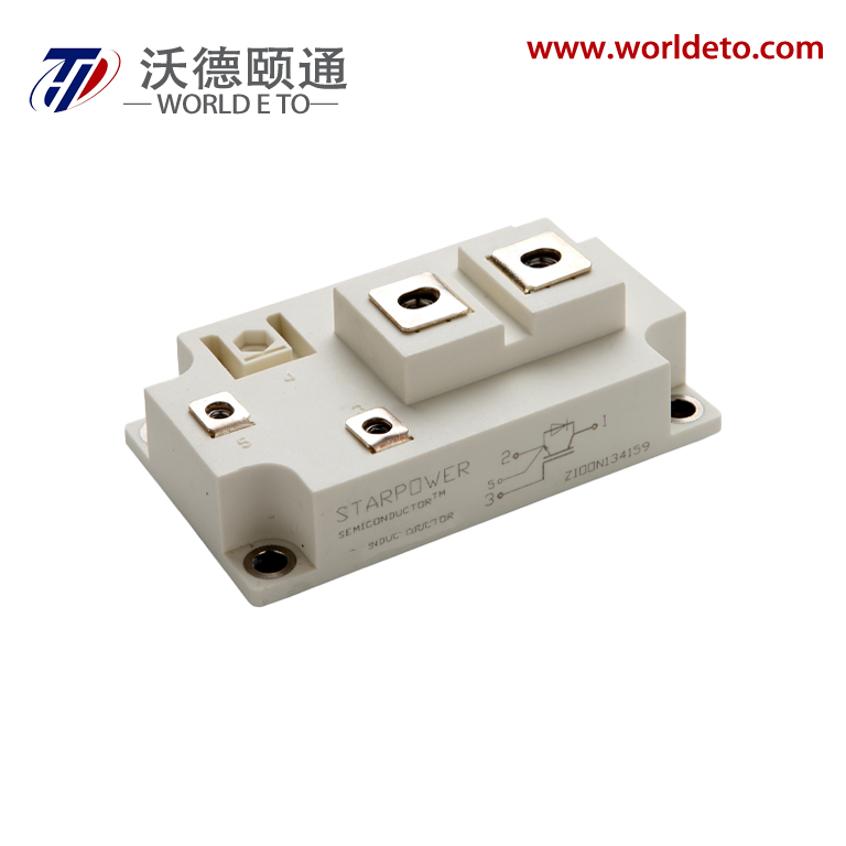
Brief introduction
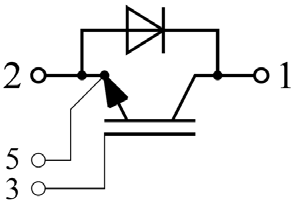
IGBT module, produced by STARPOWER. 1200V 200A.
Features
- NPT IGBT technology
- 10μs short circuit capability
- Low switching losses
- Rugged with ultrafast performance
- VCE(sat) with positive temperature coefficient
- Low inductance case
- Fast & soft reverse recovery anti-parallel FWD
- Isolated copper baseplate using DBC technology
Typical Applications
- Switching mode power supplies
- Inductive heating
- Electronic welder
Absolute Maximum Ratings TC=25℃ unless otherwise noted
Symbol |
Description |
GD200SGU120C2S |
Units |
VCES |
Collector-Emitter Voltage |
1200 |
V |
VGES |
Gate-Emitter Voltage |
±20 |
V |
IC |
Collector Current @ TC=25℃
@ TC=80℃
|
320
200
|
A |
ICM |
Pulsed Collector Current tp=1ms |
400 |
A |
IF |
Diode Continuous Forward Current @ TC=80℃ |
200 |
A |
IFM |
Diode Maximum Forward Current tp=1ms |
400 |
A |
PD |
Maximum Power Dissipation @ Tj=150℃ |
1645 |
W |
Tjmax |
Maximum Junction Temperature |
150 |
℃ |
TSTG |
Storage Temperature Range |
-40 to +125 |
℃ |
VISO |
Isolation Voltage RMS,f=50Hz,t=1min |
4000 |
V |
Mounting Torque |
Signal Terminal Screw:M4 |
1.1 to 2.0 |
|
Power Terminal Screw:M6 |
2.5 to 5.0 |
N.m |
Mounting Screw:M6 |
3.0 to 5.0 |
|
Electrical Characteristics of IGBT TC=25℃ unless otherwise noted
Off Characteristics
Symbol |
Parameter |
Test Conditions |
Min. |
Typ. |
Max. |
Units |
V(BR)CES |
Collector-Emitter
Breakdown Voltage
|
Tj=25℃ |
1200 |
|
|
V |
ICES |
Collector Cut-Off
Current
|
VCE=VCES,VGE=0V, Tj=25℃ |
|
|
5.0 |
mA |
IGES |
Gate-Emitter Leakage Current |
VGE=VGES,VCE=0V, Tj=25℃ |
|
|
400 |
nA |
On Characteristics
Symbol |
Parameter |
Test Conditions |
Min. |
Typ. |
Max. |
Units |
VGE(th) |
Gate-Emitter Threshold Voltage |
IC=2.0mA,VCE=VGE, Tj=25℃ |
4.4 |
4.9 |
6.0 |
V |
|
VCE(sat)
|
Collector to Emitter
Saturation Voltage
|
IC=200A,VGE=15V, Tj=25℃ |
|
3.10 |
3.55 |
V
|
IC=200A,VGE=15V, Tj=125℃ |
|
3.45 |
|
Switching Characteristics
Symbol |
Parameter |
Test Conditions |
Min. |
Typ. |
Max. |
Units |
td(on) |
Turn-On Delay Time |
VCC=600V,IC=200A, RG=4.7Ω,VGE=±15V, Tj=25℃
|
|
577 |
|
ns |
tr |
Rise Time |
|
120 |
|
ns |
td(off) |
Turn-Off Delay Time |
|
540 |
|
ns |
tf |
Fall Time |
|
123 |
|
ns |
Eon |
Turn-On Switching Loss |
|
16.3 |
|
mJ |
Eoff |
Turn-Off Switching Loss |
|
12.0 |
|
mJ |
td(on) |
Turn-On Delay Time |
VCC=600V,IC=200A, RG=4.7Ω,VGE=±15V, Tj=125℃
|
|
609 |
|
ns |
tr |
Rise Time |
|
121 |
|
ns |
td(off) |
Turn-Off Delay Time |
|
574 |
|
ns |
tf |
Fall Time |
|
132 |
|
ns |
Eon |
Turn-On Switching Loss |
|
22.0 |
|
mJ |
Eoff |
Turn-Off Switching Loss |
|
16.2 |
|
mJ |
Cies |
Input Capacitance |
VCE=30V,f=1MHz,
VGE=0V
|
|
16.9 |
|
nF |
Coes |
Output Capacitance |
|
1.51 |
|
nF |
Cres |
Reverse Transfer
Capacitance
|
|
0.61 |
|
nF |
|
ISC
|
SC Data
|
tP≤10μs,VGE=15 V,
Tj=125℃,VCC=900V, VCEM≤1200V
|
|
1800
|
|
A
|
LCE |
Stray Inductance |
|
|
|
20 |
nH |
|
RCC’+EE’
|
Module Lead
Resistance,
Terminal To Chip
|
|
|
0.18
|
|
mΩ
|
Electrical Characteristics of DIODE TC=25℃ unless otherwise noted
Symbol |
Parameter |
Test Conditions |
Min. |
Typ. |
Max. |
Units |
VF |
Diode Forward
Voltage
|
IF=200A |
Tj=25℃ |
|
1.82 |
2.25 |
V |
Tj=125℃ |
|
1.92 |
|
Qr |
Recovered
Charge
|
IF=200A,
VR=600V,
RG=4.7Ω,
VGE=-15V
|
Tj=25℃ |
|
13.1 |
|
μC |
Tj=125℃ |
|
26.1 |
|
IRM |
Peak Reverse
Recovery Current
|
Tj=25℃ |
|
123 |
|
A |
Tj=125℃ |
|
172 |
|
Erec |
Reverse Recovery Energy |
Tj=25℃ |
|
7.0 |
|
mJ |
Tj=125℃ |
|
12.9 |
|
Thermal Characteristics
Symbol |
Parameter |
Typ. |
Max. |
Units |
RθJC |
Junction-to-Case (per IGBT) |
|
0.076 |
K/W |
RθJC |
Junction-to-Case (per DIODE) |
|
0.128 |
K/W |
RθCS |
Case-to-Sink (Conductive grease applied) |
0.035 |
|
K/W |
Weight |
Weight Module |
300 |
|
g |