
 EN
EN
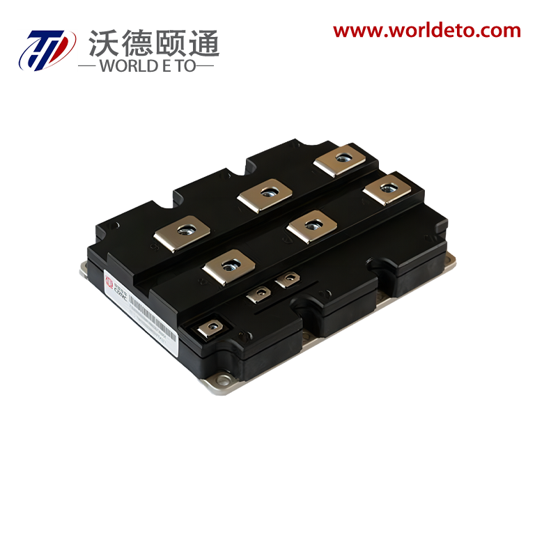
Managing heat in a compact IGBT module is one of the most critical engineering challenges in modern power electronics. As switching frequencies increase and physical footprints shrink, the thermal load per unit area rises dramatically. Without a well-designed thermal management strategy, an IGBT module can experience accelerated degradation, reduced switching efficiency, and ultimately catastrophic failure. Engineers and system designers must treat heat dissipation as a first-class design constraint alongside electrical performance.
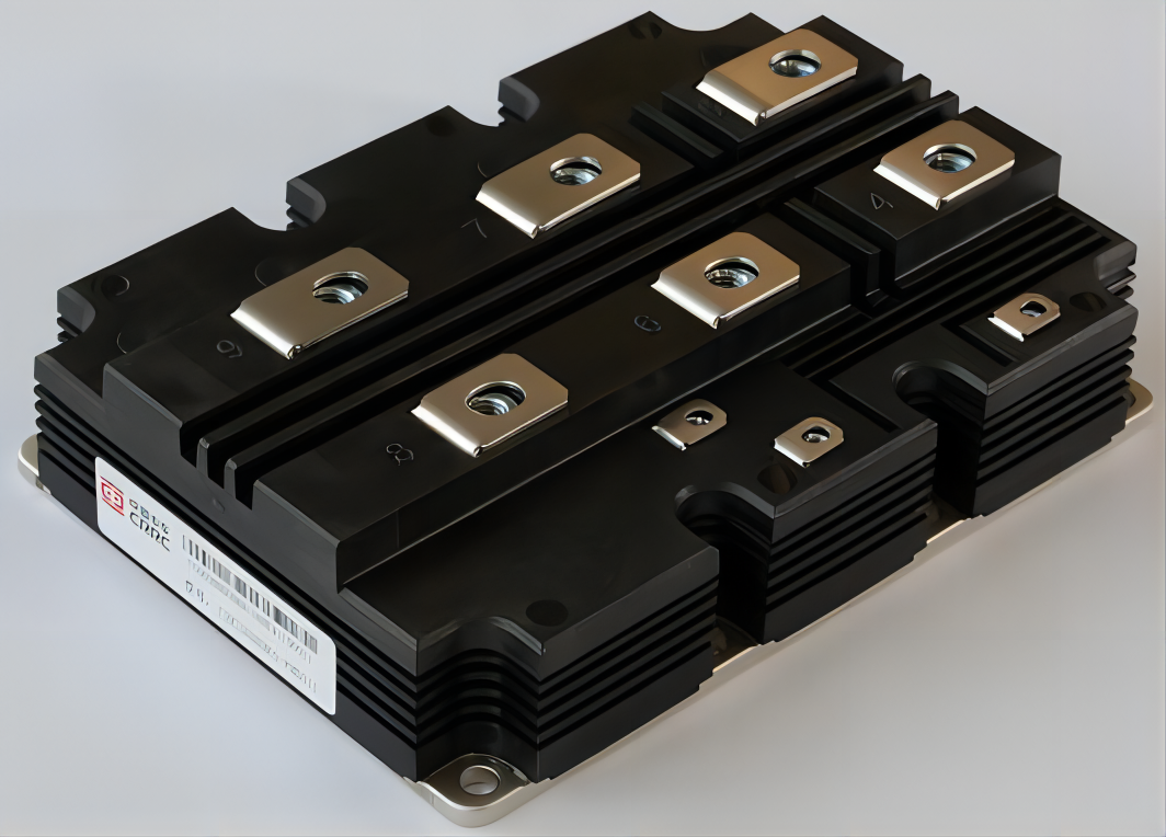
A compact IGBT module must balance high current density with strict junction temperature limits, typically capped at 150°C to 175°C depending on the device rating. When thermal resistance accumulates across the die, solder layer, substrate, thermal interface material, and heatsink, even modest power losses can push junction temperatures beyond safe limits. Understanding each layer of the thermal stack and optimizing its contribution is essential to achieving reliable long-term operation of any IGBT module in demanding industrial, traction, or renewable energy applications.
Thermal Stack Architecture of a Compact IGBT Module
Understanding the Layered Thermal Path
The thermal path within a compact IGBT module travels from the silicon die through multiple bonded layers before reaching the external cooling system. Each interface in this stack introduces thermal resistance that compounds with the others. The die itself generates heat during conduction and switching losses, and this heat must flow efficiently through the solder or sintered bond layer, the insulated metal substrate, and the baseplate before it can be transferred to a heatsink or cold plate. Any weakness in this chain directly elevates the IGBT module junction temperature under load.
In compact IGBT module designs, the substrate material plays a particularly important role. Direct bonded copper substrates offer excellent thermal conductivity and low thermal resistance compared to standard FR4-based alternatives. Active metal brazed substrates further improve mechanical robustness under thermal cycling, which is essential for IGBT module applications that experience repeated power surges. Selecting the right substrate for a given IGBT module is not just a materials decision — it is a reliability decision that affects the entire service life of the assembly.
Thermal Interface Materials and Their Impact
Thermal interface materials, commonly called TIMs, fill microscopic air gaps between the IGBT module baseplate and the heatsink surface. Even small air pockets act as thermal insulators and significantly raise overall thermal resistance. Phase-change materials, graphite pads, and thermally conductive greases are common choices for IGBT module assemblies. The right TIM selection depends on mounting pressure, surface flatness, expected temperature cycling range, and whether the IGBT module will require field maintenance or periodic removal.
For a compact IGBT module where baseplate area is limited, minimizing the bond line thickness of the TIM is critical. Thinner bond lines reduce thermal resistance, but they require very flat mating surfaces and controlled torque on mounting fasteners. Engineers must specify flatness tolerances on both the IGBT module baseplate and the heatsink surface to ensure consistent TIM performance across a production run. Poor surface preparation is one of the most common causes of unexpected thermal failures in field-deployed IGBT module systems.
Active and Passive Cooling Strategies for IGBT Module Designs
Passive Cooling Approaches and Their Limits
Passive cooling relies on natural convection and radiation to remove heat from the IGBT module without any moving parts or active fluid systems. Finned aluminum heatsinks are the most common passive solution. They work well for lower-power IGBT module configurations where switching losses are moderate and ambient conditions are stable. However, as the IGBT module power rating increases or the enclosure becomes more thermally sealed, passive cooling quickly reaches its limits. Larger fin arrays can help, but physical size constraints in compact IGBT module designs often make this approach impractical.
For an IGBT module operating at several kilowatts of continuous power dissipation, passive cooling alone is rarely sufficient. Thermal resistance from the junction to ambient must remain low enough to keep the die temperature within rated limits under worst-case load conditions. Designers must calculate worst-case power loss scenarios for the IGBT module and verify that the passive thermal path can handle the load before committing to a passive-only approach. Simulation tools that model steady-state and transient thermal behavior of the IGBT module are strongly recommended during early design stages.
Liquid Cooling and Advanced Thermal Solutions
Liquid cooling is the most effective thermal management strategy for high-power or high-frequency IGBT module applications. Cold plates mounted directly beneath the IGBT module baseplate allow coolant to flow through internal channels, extracting heat with much greater efficiency than air-based methods. Deionized water and water-glycol mixtures are common coolants used in IGBT module cold plate systems. The thermal resistance from the IGBT module junction to coolant can be reduced significantly compared to air-cooled systems, enabling higher power densities in the same footprint.
Some advanced IGBT module designs integrate microstructured or pin-fin cold plate channels directly beneath the substrate, eliminating the baseplate entirely and reducing thermal resistance at the cost of increased system complexity. Double-sided cooling, where both the top and bottom of the IGBT module silicon die are cooled simultaneously, is an emerging technique used in automotive and high-performance industrial IGBT module applications. These approaches demand careful mechanical design to avoid stress on the IGBT module substrate during thermal cycling.
Thermal Monitoring and Reliability Considerations
Junction Temperature Monitoring for IGBT Module Systems
Real-time thermal monitoring is a key enabler of reliable IGBT module operation. Gate driver circuits can incorporate negative temperature coefficient thermistor readings or on-chip temperature sensors built into the IGBT module to estimate junction temperature during operation. When junction temperature approaches the rated limit, control systems can reduce switching frequency, limit gate drive current, or trigger protective shutdowns to prevent IGBT module damage. Proactive thermal management through monitoring significantly extends service intervals and reduces unplanned downtime in systems that rely on the IGBT module.
Thermal Fatigue and Lifetime Estimation
Thermal cycling is a primary driver of IGBT module wear-out failure. Each power cycle causes expansion and contraction of bonded materials with different coefficients of thermal expansion, gradually accumulating stress in solder joints and wire bonds. For a compact IGBT module used in applications with frequent load changes — such as motor drives, solar inverters, or uninterruptible power supplies — thermal fatigue must be accounted for in the system lifetime model. Design engineers use power cycling test data and Coffin-Manson-based models to estimate IGBT module lifetime under expected operating profiles. Choosing an IGBT module with sintered silver die attach and heavy copper wire bonds substantially improves thermal fatigue resistance compared to standard solder-bonded IGBT module configurations.
FAQ
What is the maximum junction temperature for a compact IGBT module?
Most compact IGBT module devices are rated for maximum junction temperatures between 150°C and 175°C. Operating closer to the rated maximum reduces the thermal margin and accelerates degradation, so system designers typically target a junction temperature at least 20°C to 30°C below the rated limit to ensure reliable IGBT module operation over the intended service life.
How does thermal interface material selection affect IGBT module reliability?
Thermal interface material directly affects the thermal resistance between the IGBT module baseplate and the heatsink. A poor TIM choice or improper application can raise the IGBT module junction temperature by 10°C or more under rated load, which significantly reduces device lifetime. Selecting a high-conductivity TIM with stable performance over temperature and time is essential for any high-reliability IGBT module installation.
Is liquid cooling always necessary for a high-power IGBT module?
Liquid cooling is not always mandatory, but it becomes necessary when the power dissipation of the IGBT module exceeds what passive or forced-air cooling can manage within the allowable thermal resistance budget. For compact IGBT module designs with high current ratings or high switching frequencies, liquid cooling provides the thermal headroom needed to maintain safe junction temperatures and achieve the best balance of performance and reliability.