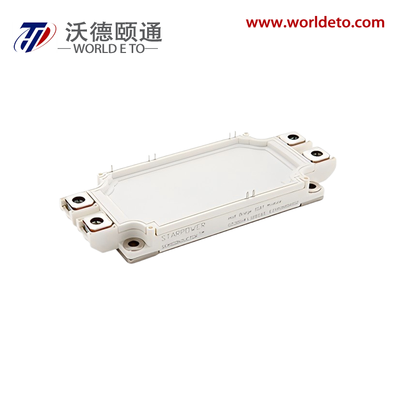
Brief introduction
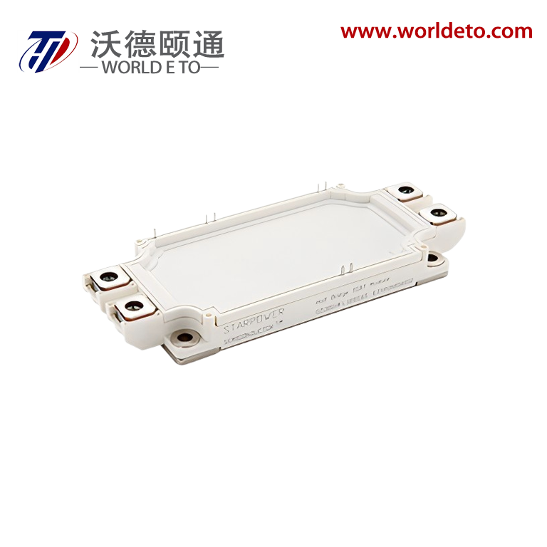
IGBT module,produced by STARPOWER. 1200V 300A.
Features
Low VCE(sat) Trench IGBT technology
10μs short circuit capability
VCE(sat) with positive temperature coefficient
Maximum junction temperature 175oC
Low inductance case
Fast & soft reverse recovery anti-parallel FWD
Isolated copper baseplate using DBC technology
Typical Applications
Inverter for motor drive
AC and DC servo drive amplifier
Uninterruptible power suppl
Absolute Maximum Ratings TF=25oC unless otherwise noted
IGBT
Symbol |
Description |
Value |
Unit |
VCES |
Collector-Emitter Voltage |
1200 |
V |
VGES |
Gate-Emitter Voltage |
±20 |
V |
IC |
Collector Current @ TC=25oC @ TC=100oC |
496
300
|
A |
ICM |
Pulsed Collector Current tp=1ms |
600 |
A |
PD |
Maximum Power Dissipation @ Tj=175oC |
1685 |
W |
Diode
Symbol |
Description |
Value |
Unit |
VRRM |
Repetitive Peak Reverse Voltage |
1200 |
V |
IF |
Diode Continuous Forward Current |
300 |
A |
IFM |
Diode Maximum Forward Current tp=1ms |
600 |
A |
Module
Symbol |
Description |
Value |
Unit |
Tjmax |
Maximum Junction Temperature |
175 |
oC |
Tjop |
Operating Junction Temperature |
-40 to +150 |
oC |
TSTG |
Storage Temperature Range |
-40 to +125 |
oC |
VISO |
Isolation Voltage RMS,f=50Hz,t=1min |
2500 |
V |
IGBT Characteristics TC=25oC unless otherwise noted
Symbol |
Parameter |
Test Conditions |
Min. |
Typ. |
Max. |
Unit |
|
VCE(sat)
|
Collector to Emitter Saturation Voltage
|
IC=300A,VGE=15V, Tj=25oC |
|
1.70 |
2.15 |
V
|
IC=300A,VGE=15V, Tj=125oC |
|
1.95 |
|
IC=300A,VGE=15V, Tj=150oC |
|
2.00 |
|
VGE(th) |
Gate-Emitter Threshold Voltage |
IC=12.0mA,VCE=VGE, Tj=25oC |
5.6 |
6.2 |
6.8 |
V |
ICES |
Collector Cut-Off Current |
VCE=VCES,VGE=0V, Tj=25oC |
|
|
1.0 |
mA |
IGES |
Gate-Emitter Leakage Current |
VGE=VGES,VCE=0V, Tj=25oC |
|
|
400 |
nA |
RGint |
Internal Gate Resistance |
|
|
2.5 |
|
Ω |
Cies |
Input Capacitance |
VCE=25V,f=1MHz, VGE=0V |
|
31.1 |
|
nF |
Cres |
Reverse Transfer Capacitance |
|
0.87 |
|
nF |
QG |
Gate Charge |
VGE=-15 …+15V |
|
2.33 |
|
μC |
td(on) |
Turn-On Delay Time |
VCC=600V,IC=300A, RG=1.5Ω,VGE=±15V, Tj=25oC
|
|
313 |
|
ns |
tr |
Rise Time |
|
57 |
|
ns |
td(off) |
Turn-Off Delay Time |
|
464 |
|
ns |
tf |
Fall Time |
|
206 |
|
ns |
Eon |
Turn-On Switching Loss |
|
9.97 |
|
mJ |
Eoff |
Turn-Off Switching Loss |
|
28.6 |
|
mJ |
td(on) |
Turn-On Delay Time |
VCC=600V,IC=300A, RG=1.5Ω,VGE=±15V, Tj=125oC
|
|
336 |
|
ns |
tr |
Rise Time |
|
66 |
|
ns |
td(off) |
Turn-Off Delay Time |
|
528 |
|
ns |
tf |
Fall Time |
|
299 |
|
ns |
Eon |
Turn-On Switching Loss |
|
21.1 |
|
mJ |
Eoff |
Turn-Off Switching Loss |
|
36.6 |
|
mJ |
td(on) |
Turn-On Delay Time |
VCC=600V,IC=300A, RG=1.5Ω,VGE=±15V, Tj=150oC
|
|
345 |
|
ns |
tr |
Rise Time |
|
68 |
|
ns |
td(off) |
Turn-Off Delay Time |
|
539 |
|
ns |
tf |
Fall Time |
|
309 |
|
ns |
Eon |
Turn-On Switching Loss |
|
25.6 |
|
mJ |
Eoff |
Turn-Off Switching Loss |
|
37.8 |
|
mJ |
|
ISC
|
SC Data
|
tP≤10μs,VGE=15V,
Tj=150oC,VCC=900V, VCEM≤1200V
|
|
1200
|
|
A
|
Diode Characteristics TC=25oC unless otherwise noted
Symbol |
Parameter |
Test Conditions |
Min. |
Typ. |
Max. |
Units |
|
VF
|
Diode Forward Voltage |
IF=300A,VGE=0V,Tj=25oC |
|
1.85 |
2.30 |
V
|
IF=300A,VGE=0V,Tj=125oC |
|
1.90 |
|
IF=300A,VGE=0V,Tj=150oC |
|
1.95 |
|
Qr |
Recovered Charge |
VCC=600V,IF=300A,
-di/dt=6950A/μs,VGE=-15V, Tj=25oC
|
|
10.8 |
|
μC |
IRM |
Peak Reverse
Recovery Current
|
|
272 |
|
A |
Erec |
Reverse Recovery Energy |
|
9.53 |
|
mJ |
Qr |
Recovered Charge |
VCC=600V,IF=300A,
-di/dt=6090A/μs,VGE=-15V, Tj=125oC
|
|
24.2 |
|
μC |
IRM |
Peak Reverse
Recovery Current
|
|
276 |
|
A |
Erec |
Reverse Recovery Energy |
|
18.4 |
|
mJ |
Qr |
Recovered Charge |
VCC=600V,IF=300A,
-di/dt=5440A/μs,VGE=-15V, Tj=150oC
|
|
33.6 |
|
μC |
IRM |
Peak Reverse
Recovery Current
|
|
278 |
|
A |
Erec |
Reverse Recovery Energy |
|
20.6 |
|
mJ |
NTC Characteristics TC=25oC unless otherwise noted
Symbol |
Parameter |
Test Conditions |
Min. |
Typ. |
Max. |
Unit |
R25 |
Rated Resistance |
|
|
5.0 |
|
kΩ |
∆R/R |
Deviation of R100 |
TC=100 oC,R100=493.3Ω |
-5 |
|
5 |
% |
P25 |
Power
Dissipation
|
|
|
|
20.0 |
mW |
B25/50 |
B-value |
R2=R25exp[B25/50(1/T2- 1/(298.15K))] |
|
3375 |
|
K |
B25/80 |
B-value |
R2=R25exp[B25/80(1/T2- 1/(298.15K))] |
|
3411 |
|
K |
B25/100 |
B-value |
R2=R25exp[B25/100(1/T2- 1/(298.15K))] |
|
3433 |
|
K |
Module Characteristics TC=25oC unless otherwise noted
Symbol |
Parameter |
Min. |
Typ. |
Max. |
Unit |
LCE |
Stray Inductance |
|
20 |
|
nH |
RCC’+EE’ |
Module Lead Resistance, Terminal to Chip |
|
1.10 |
|
mΩ |
RthJC |
Junction-to-Case (perIGBT) Junction-to-Case (per Diode) |
|
|
0.089 0.150 |
K/W |
|
RthCH
|
Case-to-Heatsink (perIGBT) Case-to-Heatsink (per Diode) Case-to-Heatsink (per Module) |
|
0.029 0.048 0.009 |
|
K/W |
M |
Terminal Connection Torque, Screw M6 Mounting Torque, Screw M5 |
3.0 3.0 |
|
6.0 6.0 |
N.m |
G |
Weight of Module |
|
350 |
|
g |