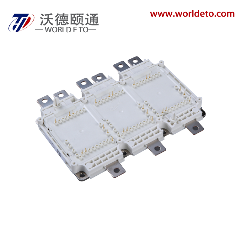
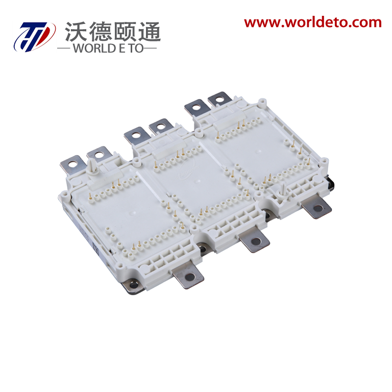
Brief introduction
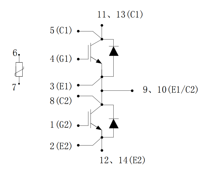
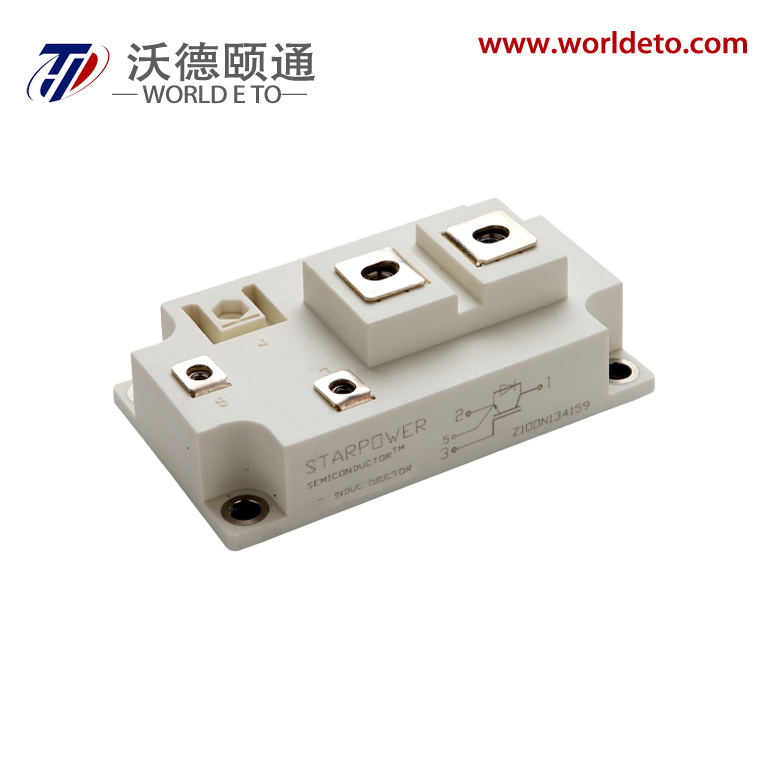
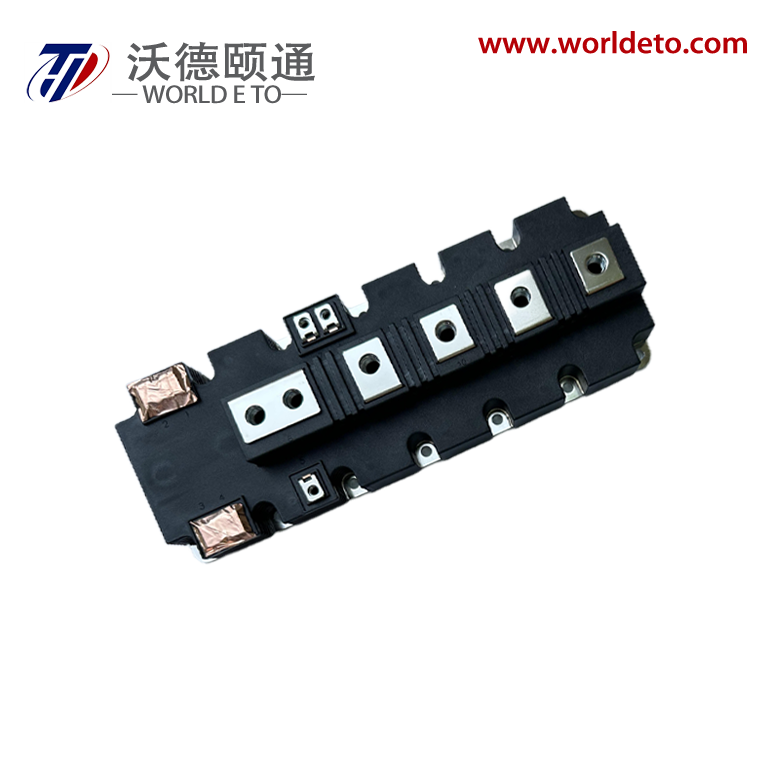
IGBT module,Half Bridge IGBT, produced by CRRC. 1700V 1800A.
Key Parameters
VCES |
1700 V |
VCE(sat) Typ. |
1.7 V |
IC Max. |
1800 A |
IC(RM) Max. |
3600 A |
Features
-
Cu Baseplate
- Enhanced Al2O3 Substrates
- VCE(sat) with positive temperature coefficient
- High Thermal Cycling Capability
-
Low VCE(sat) Device
Typical Applications
- Motor Drives
- High Power Converters
- High Reliability Inverters
- Wind Turbines
Absolute Maximum Ratings
符号 Symbol |
参数名称 Parameter |
测试条件
Test Conditions
|
数值 Value |
单位 Unit |
VCES |
集电极-发射极电压
Collector-emitter voltage
|
VGE = 0V, TC= 25 °C |
1700 |
V |
VGES |
栅极-发射极电压
Gate-emitter voltage
|
TC= 25 °C |
± 20 |
V |
IC |
集电极电流
Collector-emitter current
|
TC = 85 °C, Tvj max = 175°C |
1800 |
A |
IC(PK) |
集电极峰值电流
Peak collector current
|
tP=1ms |
3600 |
A |
Pmax |
晶体管部分最大损耗
Max. transistor power dissipation
|
Tvj = 175°C, TC = 25 °C |
9.38 |
kW |
I2t |
二极管 I2t 值 Diode I2t |
VR =0V, tP = 10ms, Tvj = 175 °C |
551 |
kA2s |
|
Visol
|
绝缘电压(模块)
Isolation voltage - per module
|
短接所有端子,端子与基板间施加电压 ( Connected terminals to base plate), AC RMS,1 min, 50Hz, TC= 25 °C |
4000
|
V
|
Thermal & Mechanical Data
参数 Symbol |
说明
Explanation
|
值 Value |
单位 Unit |
|
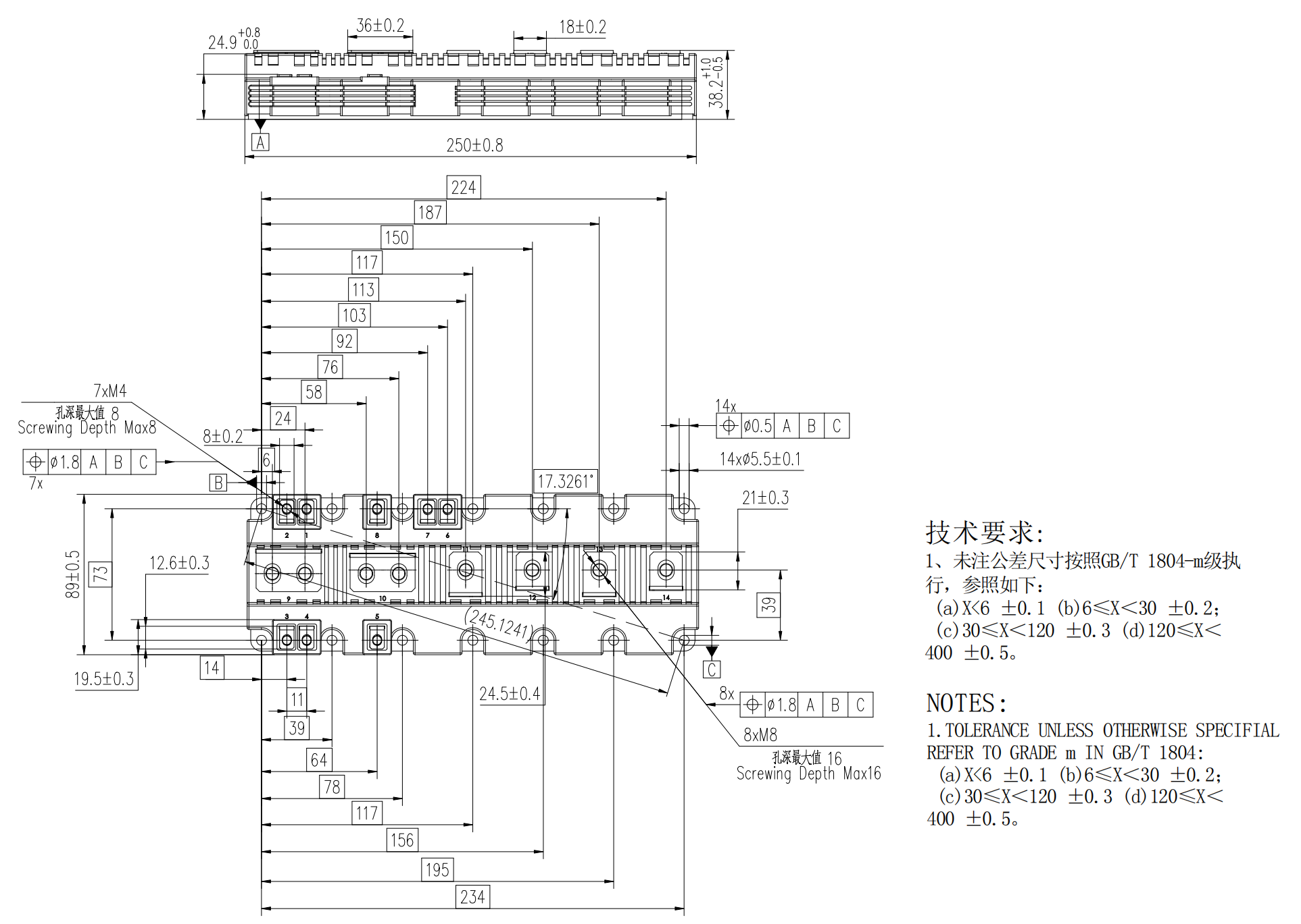
|
爬电距离
Creepage distance
|
端子-散热器
Terminal to heatsink
|
36.0 |
mm |
|
|
端子-端子
Terminal to terminal
|
28.0 |
mm |
|
|
绝缘间隙 Clearance
|
端子-散热器
Terminal to heatsink
|
21.0 |
mm |
|
|
端子-端子
Terminal to terminal
|
19.0 |
mm |
|
|
相对漏电起痕指数
CTI (Comparative Tracking Index)
|
|
400 |
|
|
|
符号 Symbol |
参数名称 Parameter |
测试条件
Test Conditions
|
最小值 Min. |
典型值 Typ. |
最大值 Max. |
单位 Unit |
|
Rth(J-C) IGBT |
IGBT 结壳热阻
Thermal resistance – IGBT
|
|
|
|
16 |
K / kW |
|
Rth(J-C) Diode
|
二极管结壳热阻
Thermal resistance – Diode
|
|
|
33
|
K / kW
|
|
Rth(C-H) IGBT
|
接触热阻(IGBT)
Thermal resistance –
case to heatsink (IGBT)
|
安装力矩 5Nm, 导热脂 1W/m·K Mounting torque 5Nm,
with mounting grease 1W/m·K
|
|
14
|
|
K / kW
|
|
Rth(C-H) Diode |
接触热阻(Diode)
Thermal resistance –
case to heatsink (Diode)
|
安装力矩 5Nm, 导热脂 1W/m·K Mounting torque 5Nm,
with mounting grease 1W/m·K
|
|
17
|
|
K / kW |
|
Tvjop |
工作结温
Operating junction temperature
|
IGBT 芯片 ( IGBT ) |
-40 |
|
150 |
°C |
|
二极管芯片( Diode ) |
-40 |
|
150 |
°C |
|
Tstg |
存储温度
Storage temperature range
|
|
-40 |
|
150 |
°C |
|
M
|
安装力矩
Screw torque
|
安装紧固用– M5 Mounting – M5 |
3 |
|
6 |
Nm |
|
电路互连用– M4
Electrical connections – M4
|
1.8 |
|
2.1 |
Nm |
|
电路互连用– M8
Electrical connections – M8
|
8 |
|
10 |
Nm |
Thermal & Mechanical Data
符号 Symbol |
参数名称 Parameter |
测试条件
Test Conditions
|
最小值 Min. |
典型值 Typ. |
最大值 Max. |
单位 Unit |
Rth(J-C) IGBT |
IGBT 结壳热阻
Thermal resistance – IGBT
|
|
|
|
16 |
K / kW |
|
Rth(J-C) Diode
|
二极管结壳热阻
Thermal resistance – Diode
|
|
|
33
|
K / kW
|
|
Rth(C-H) IGBT
|
接触热阻(IGBT)
Thermal resistance –
case to heatsink (IGBT)
|
安装力矩 5Nm, 导热脂 1W/m·K Mounting torque 5Nm,
with mounting grease 1W/m·K
|
|
14
|
|
K / kW
|
Rth(C-H) Diode |
接触热阻(Diode)
Thermal resistance –
case to heatsink (Diode)
|
安装力矩 5Nm, 导热脂 1W/m·K Mounting torque 5Nm,
with mounting grease 1W/m·K
|
|
17
|
|
K / kW |
Tvjop |
工作结温
Operating junction temperature
|
IGBT 芯片 ( IGBT ) |
-40 |
|
150 |
°C |
二极管芯片( Diode ) |
-40 |
|
150 |
°C |
Tstg |
存储温度
Storage temperature range
|
|
-40 |
|
150 |
°C |
|
M
|
安装力矩
Screw torque
|
安装紧固用– M5 Mounting – M5 |
3 |
|
6 |
Nm |
|
电路互连用– M4
Electrical connections – M4
|
1.8 |
|
2.1 |
Nm |
|
电路互连用– M8
Electrical connections – M8
|
8 |
|
10 |
Nm |
NTC-Thermistor Data
符号 Symbol |
参数名称 Parameter |
测试条件
Test Conditions
|
最小值 Min. |
典型值 Typ. |
最大值 Max. |
单位 Unit |
R25 |
额定电阻值
Rated resistance
|
TC = 25 °C |
|
5 |
|
kΩ |
△R/R |
R100 偏差
Deviation of R100
|
TC = 100 °C, R100=493Ω |
-5 |
|
5 |
% |
P25 |
耗散功率
Power dissipation
|
TC = 25 °C |
|
|
20 |
mW |
B25/50 |
B-值
B-value
|
R2 = R25exp [B25/50(1/T2 - 1/(298.15 K))] |
|
3375 |
|
K |
B25/80 |
B-值
B-value
|
R2 = R25exp [B25/80(1/T2 - 1/(298.15 K))] |
|
3411 |
|
K |
B25/100 |
B-值
B-value
|
R2 = R25exp [B25/100(1/T2 - 1/(298.15 K))] |
|
3433 |
|
K |
Electrical Characteristics
符号 Symbol |
参数名称 Parameter |
条件
Test Conditions
|
最小值 Min. |
典型值 Typ. |
最大值 Max. |
单位 Unit |
|
|
ICES
|
集电极截止电流
Collector cut-off current
|
VGE = 0V,VCE = VCES |
|
|
1 |
mA |
|
VGE = 0V, VCE = VCES, Tvj =150 °C |
|
|
40 |
mA |
|
VGE = 0V, VCE = VCES, Tvj =175 °C |
|
|
60 |
mA |
|
IGES |
栅极漏电流
Gate leakage current
|
VGE = ±20V, VCE = 0V |
|
|
0.5 |
μA |
|
VGE (th) |
栅极-发射极阈值电压 Gate threshold voltage |
IC = 60mA, VGE = VCE |
5.1 |
5.7 |
6.3 |
V |
|
|
VCE (sat)(*1)
|
集电极-发射极饱和电压
Collector-emitter saturation
voltage
|
VGE =15V, IC = 1800A |
|
1.70 |
|
V |
|
VGE =15V, IC = 1800A, Tvj = 150 °C |
|
2.10 |
|
V |
|
VGE =15V, IC = 1800A, Tvj = 175 °C |
|
2.15 |
|
V |
|
IF |
二极管正向直流电流 Diode forward current |
DC |
|
1800 |
|
A |
|
IFRM |
二极管正向重复峰值电流 Diode peak forward current |
tP = 1ms |
|
3600 |
|
A |
|
|
VF(*1)
|
二极管正向电压
Diode forward voltage
|
IF = 1800A, VGE = 0 |
|
1.60 |
|
V |
|
IF = 1800A, VGE = 0, Tvj = 150 °C |
|
1.75 |
|
V |
|
IF = 1800A, VGE = 0, Tvj = 175 °C |
|
1.75 |
|
V |
|
|
ISC
|
短路电流
Short circuit current
|
Tvj = 175°C, VCC = 1000V, VGE ≤15V, tp ≤10μs,
VCE(max) = VCES – L(*2) ×di/dt, IEC 60747-9
|
|
7400
|
|
A
|
|
|
Cies |
输入电容
Input capacitance
|
VCE = 25V, VGE = 0V, f = 100kHz |
|
542 |
|
nF |
|
Qg |
栅极电荷
Gate charge
|
±15V |
|
23.6 |
|
μC |
|
Cres |
反向传输电容
Reverse transfer capacitance
|
VCE = 25V, VGE = 0V, f = 100kHz |
|
0.28 |
|
nF |
|
LsCE |
模块杂散电感
Module stray inductance
|
|
|
8.4 |
|
nH |
|
RCC’+EE’ |
模块引线电阻,端子-芯片 Module lead resistance, terminal-chip |
每开关
per switch
|
|
0.20 |
|
mΩ |
|
RGint |
内部栅极电阻
Internal gate resistor
|
|
|
1 |
|
Ω |
Electrical Characteristics
符号 Symbol |
参数名称 Parameter |
测试条件
Test Conditions
|
最小值 Min. |
典型值 Typ. |
最大值 Max. |
单位 Unit |
|
td(off)
|
关断延迟时间
Turn-off delay time
|
IC =1800A,
VCE = 900V,
VGE = ±15V, RG(OFF) = 0.5Ω, LS = 25nH,
dv/dt =3800V/μs (Tvj= 150 °C).
|
Tvj= 25 °C |
|
1000 |
|
ns
|
Tvj= 150 °C |
|
1200 |
|
Tvj= 175 °C |
|
1250 |
|
|
tf
|
下降时间 Fall time
|
Tvj= 25 °C |
|
245 |
|
ns
|
Tvj= 150 °C |
|
420 |
|
Tvj= 175 °C |
|
485 |
|
|
EOFF
|
关断损耗
Turn-off energy loss
|
Tvj= 25 °C |
|
425 |
|
mJ
|
Tvj= 150 °C |
|
600 |
|
Tvj= 175 °C |
|
615 |
|
|
td(on)
|
开通延迟时间
Turn-on delay time
|
IC =1800A,
VCE = 900V,
VGE = ±15V, RG(ON) = 0.5Ω, LS = 25nH,
di/dt = 8500A/μs (Tvj= 150 °C).
|
Tvj= 25 °C |
|
985 |
|
ns
|
Tvj= 150 °C |
|
1065 |
|
Tvj= 175 °C |
|
1070 |
|
|
tr
|
上升时间 Rise time
|
Tvj= 25 °C |
|
135 |
|
ns
|
Tvj= 150 °C |
|
205 |
|
Tvj= 175 °C |
|
210 |
|
|
EON
|
开通损耗
Turn-on energy loss
|
Tvj= 25 °C |
|
405 |
|
mJ
|
Tvj= 150 °C |
|
790 |
|
Tvj= 175 °C |
|
800 |
|
|
Qrr
|
二极管反向恢复电荷 Diode reverse
recovery charge
|
IF =1800A, VCE = 900V,
- diF/dt = 8500A/μs (Tvj= 150 °C).
|
Tvj= 25 °C |
|
420 |
|
μC
|
Tvj= 150 °C |
|
695 |
|
Tvj= 175 °C |
|
710 |
|
|
Irr
|
二极管反向恢复电流 Diode reverse
recovery current
|
Tvj= 25 °C |
|
1330 |
|
A
|
Tvj= 150 °C |
|
1120 |
|
Tvj= 175 °C |
|
1100 |
|
|
Erec
|
二极管反向恢复损耗 Diode reverse
recovery energy
|
Tvj= 25 °C |
|
265 |
|
mJ
|
Tvj= 150 °C |
|
400 |
|
Tvj= 175 °C |
|
420 |
|