1 |
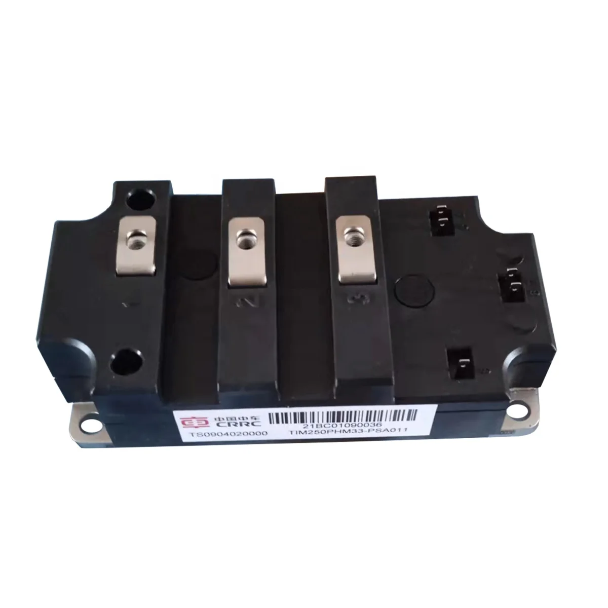
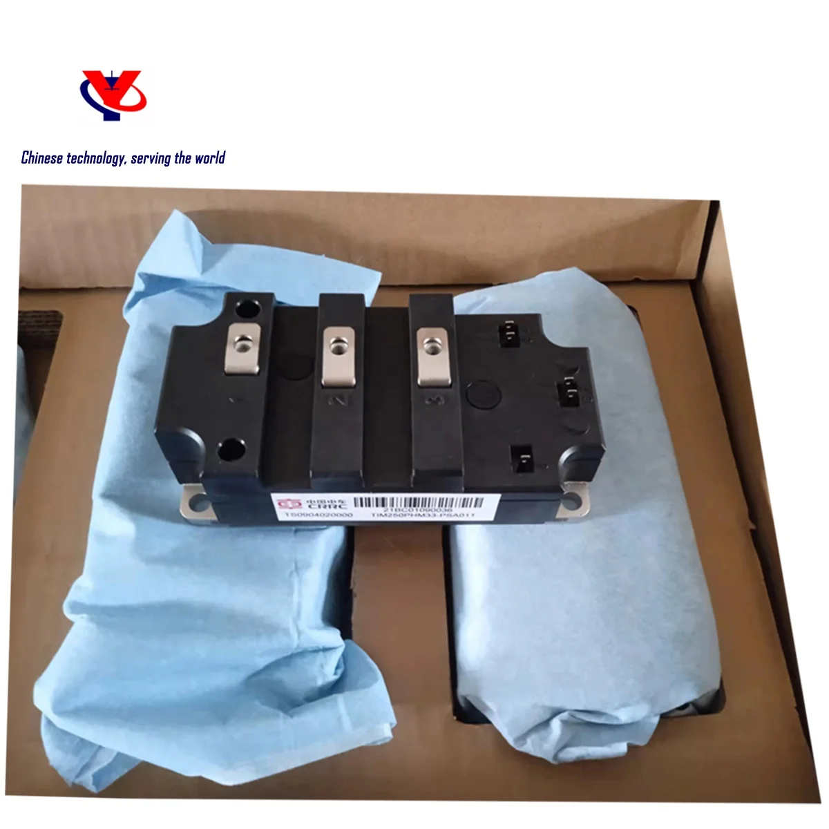
IGBT module and Driver |
2 |
IGCT module and Driver |
3 |
FRD module |
4 |
Diode module |
5 |
Thyristors module |
6 |
Current sensor |
7 |
Capacitor |
8 |
Resistor |
9 |
Solid state relay |
10 |
Industrial robots and Core parts |
11 |
Civil Unmanned Aircraft and Core Parts |

Symbol |
Description |
Value |
Unit |
VCES |
3300 |
V |
|
VCE(sat)
|
Typ. |
2.5 |
V |
IC
|
Max. |
250 |
A |
IC(RM)
|
IC(RM) |
500 |
A |
Symbol |
Description |
Value |
Unit |
VCES |
Collector-Emitter Voltage |
3300 |
V |
VGES |
Gate-Emitter Voltage |
±20 |
V |
IC |
Collector Current @ TC=100℃ |
250 |
A |
IC(PK) |
Pulsed Collector Current tp=1ms |
500 |
A |
Pmax
|
Max. transistor power dissipation Tvj = 150°C, TC = 25 °C |
2600 |
W |
I 2 t |
Diode I 2 t VR =0V, tP = 10ms, Tvj = 150 °C
|
20 |
kA2 s |
Visol
|
Isolation voltage – per module ( Commoned terminals to baseplate),
AC RMS,1 min, 50Hz,TC= 25 °C |
6000 |
W |
QPD
|
Partial discharge – per module IEC1287.V1=6900V,V2=5100V,50Hz RMS
|
10 |
pC |
Symbol |
Explanation |
Value |
Unit |
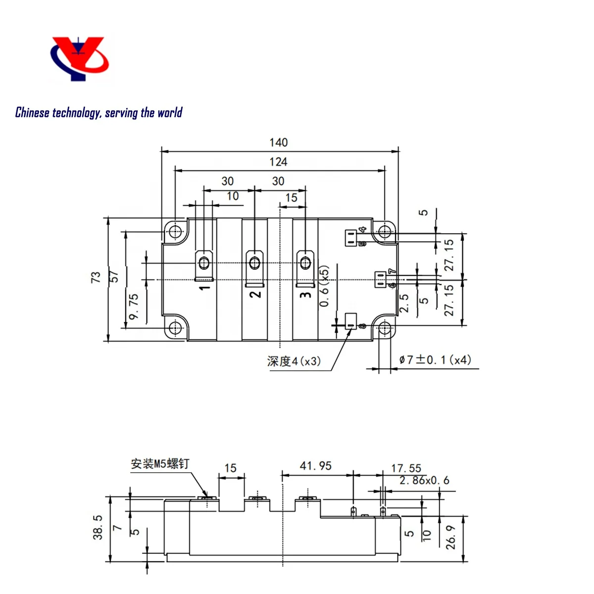
Creepage distance |
Terminal to heatsink |
33.0 |
mm |
Terminal to terminal |
33.0 |
mm |
|
Clearance |
Terminal to heatsink |
20.0 |
mm |
Terminal to terminal |
20.0 |
mm |
|
CTI (Comparative Tracking Index) |
Diode Maximum Forward Current tp=1ms |
>600 |
Symbol |
Parameter |
Test Conditions |
Min. |
Max. |
Value |
Unit |
|
Rth(J-C) IGBT |
Thermal resistance – IGBT |
48 |
K / kW |
℃ |
|||
Rth(J-C) Diode |
Thermal resistance – Diode |
80 |
K / kW |
℃ |
|||
Rth(C-H) IGBT |
Thermal resistance – case to heatsink (IGBT) |
Mounting torque 5Nm, with mounting grease 1W/m·°C |
18 |
K / kW |
℃ |
||
Rth(C-H) Diode |
Thermal resistance – case to heatsink (Diode) |
Mounting torque 5Nm, with mounting grease 1W/m·°C |
36 |
K / kW |
V |
||
Tvj op
|
Operating junction temperature |
IGBT |
-40 |
150 |
°C |
||
Diode |
-40 |
150 |
°C |
||||
M |
Screw torque |
Mounting –M6 |
5 |
nM |
|||
Electrical connections –M5 |
4 |
nM |
Symbol |
Parameter |
Test Conditions |
Min. |
Typ. |
Max. |
Unit |
ICES
|
Collector cut-off current |
VGE = 0V,VCE = VCES
|
1 |
mA |
||
VGE = 0V, VCE = VCES, TC=125 °C |
15 |
mA |
||||
VGE = 0V, VCE = VCES, TC=150 °C |
25 |
mA |
||||
IGES
|
Gate leakage current |
VGE = ±20V, VCE = 0V |
1 |
μA |
||
VGE (TH)
|
Gate threshold voltage |
IC = 20mA, VGE = VCE |
5.5 |
6.1 |
7.0 |
V |
VCE (sat)
|
Collector-emitter saturation voltage |
VGE =15V, IC = 250A |
||||
VGE =15V, IC = 250A,Tvj = 125 °C |
||||||
VGE =15V, IC = 250A,Tvj = 125 °C |
||||||
IF
|
Diode forward current |
DC |
250 |
A |
||
IFRM
|
Diode peak forward current |
tP = 1ms |
500 |
A |
||
VF
|
Diode forward voltage |
IF = 250A, VGE = 0 |
2.10 |
2.40 |
V |
|
IF = 250A, VGE = 0, Tvj = 125 °C |
2.25 |
2.25 |
V |
|||
IF = 250A, VGE = 0, Tvj = 150 °C |
2.25 |
2.25 |
V |
|||
ISC
|
Short circuit current |
Tvj = 150° C, VCC = 2500V, VGE≤15V, tp≤10μs, VCE(max) = VCES – L (*2)×di/dt, IEC 6074 |
900 |
A |
||
Cies |
Input capacitance |
VCE = 25V, VGE = 0V, f = 100kHz |
27 |
nF |
||
Qg |
Gate charge |
±15 |
2.6 |
V |
||
Cres |
Reverse transfer capacitance |
VCE = 25V, VGE = 0V, f = 100kHz |
0.9 |
nF |
||
LM
|
Module inductance |
40 |
nH |
|||
RINT
|
Internal transistor resistance |
0.5 |
mΩ |


Our professional sales team are waiting for your consultation.
You can follow their product list and ask any questions you care about.