1 |
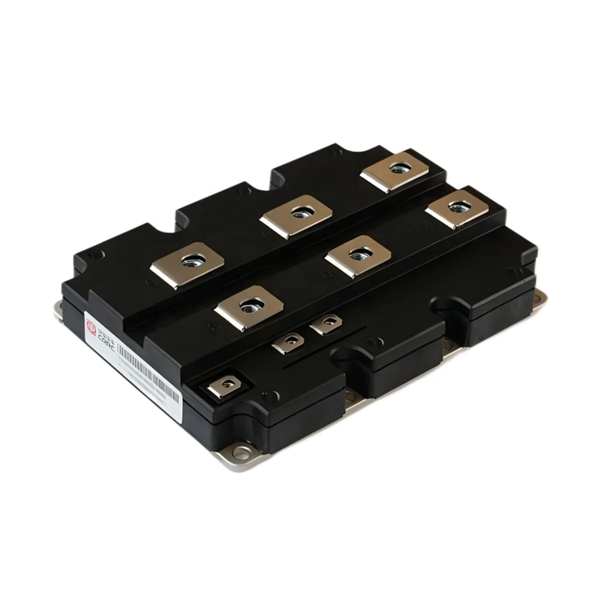
IGBT module and Driver |
2 |
IGCT module and Driver |
3 |
Inverter core board |
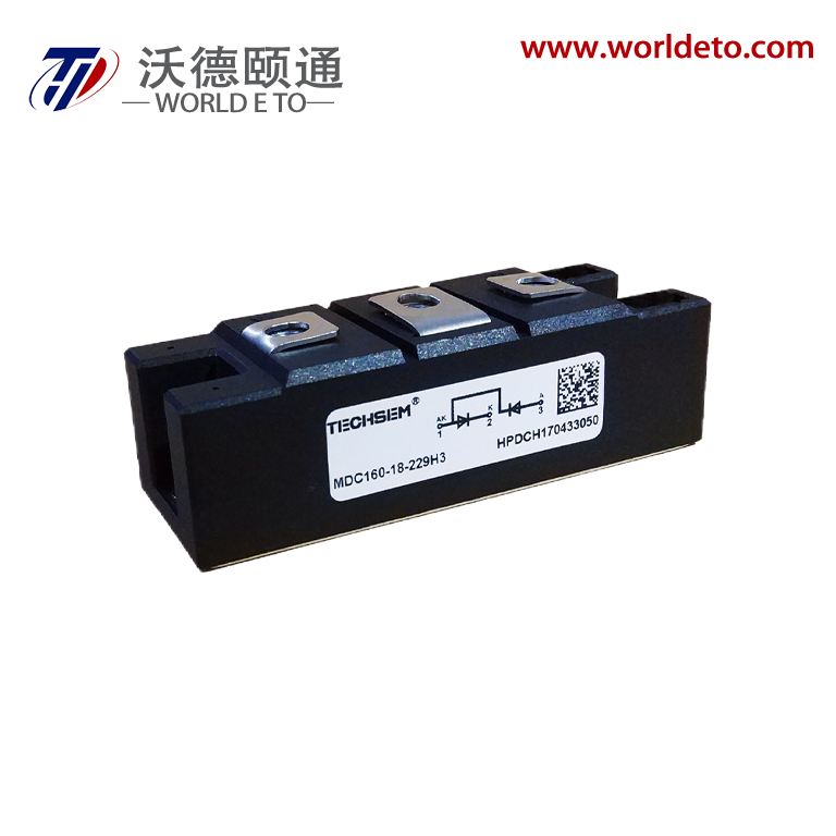
4 |
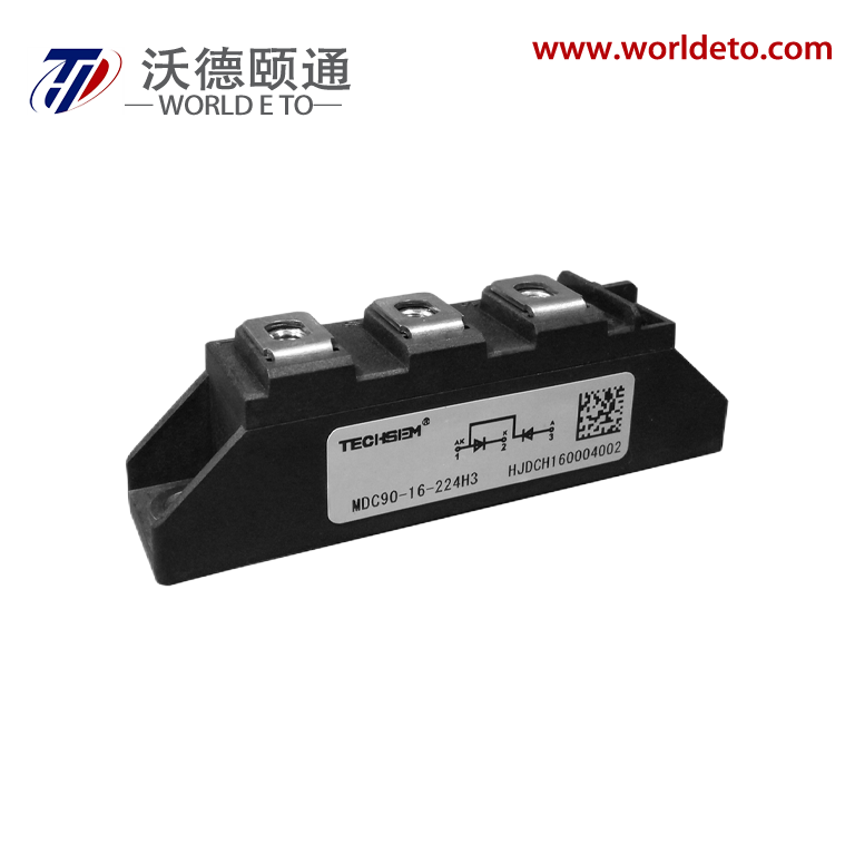
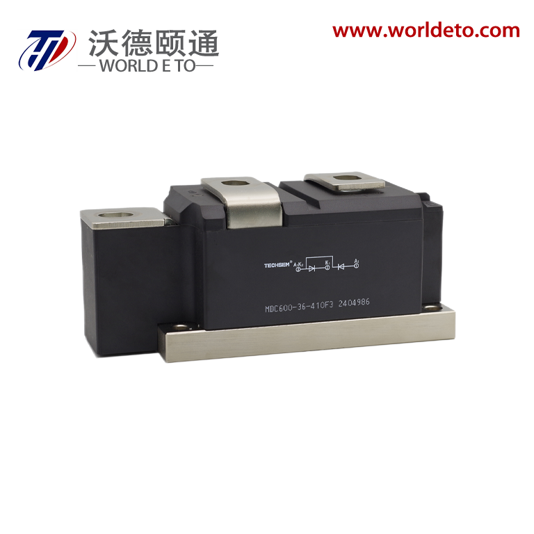
Diode module |
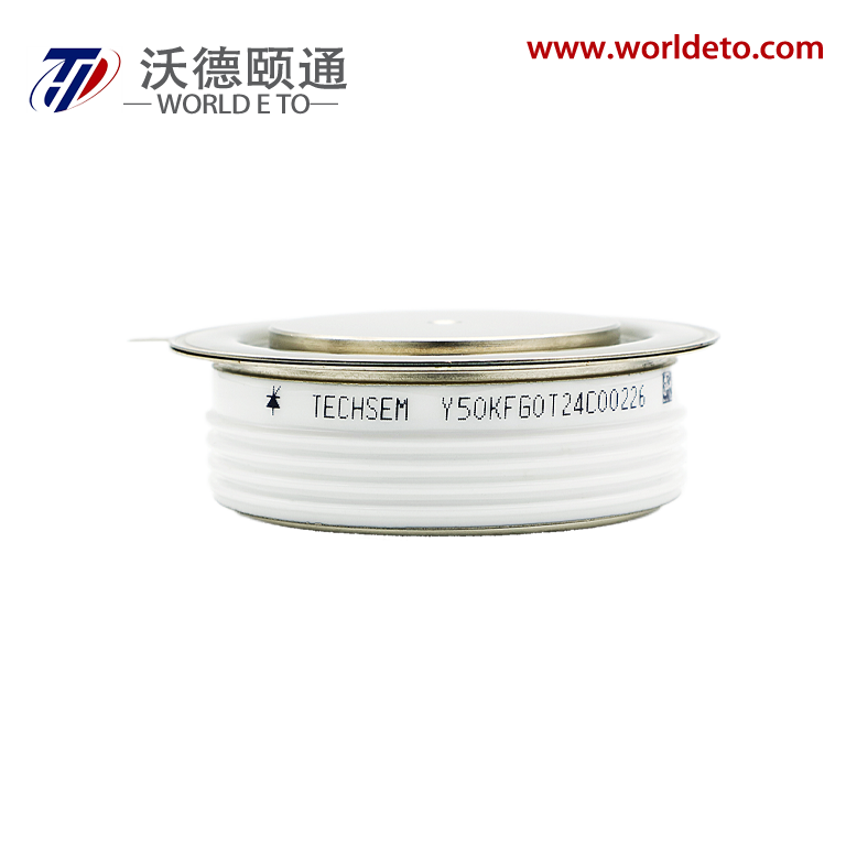
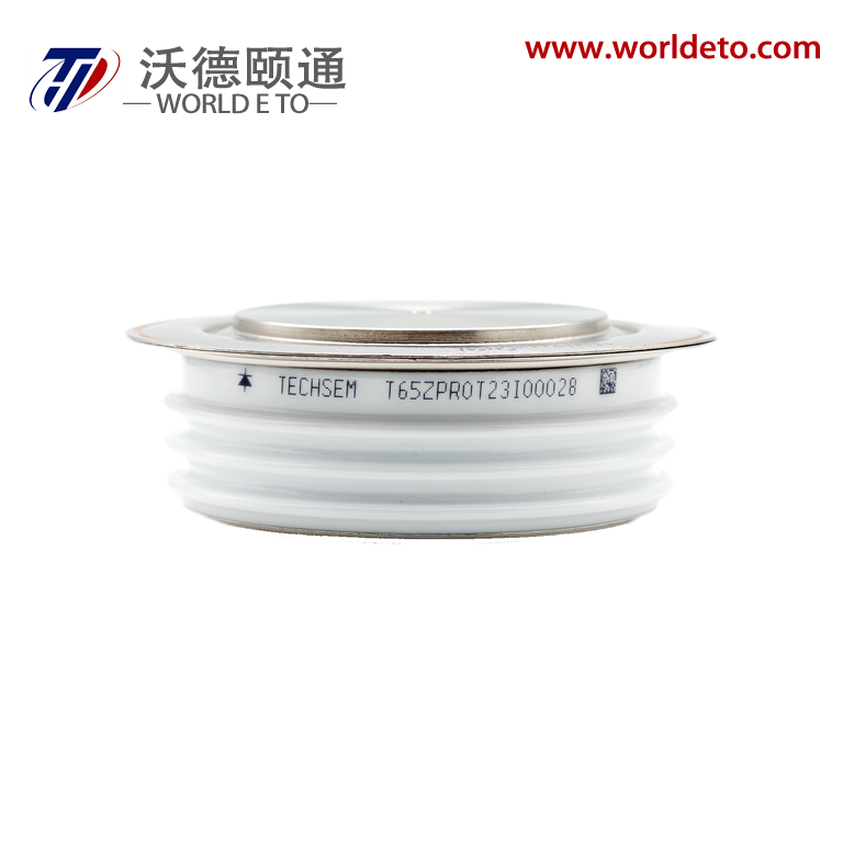
5 |
Thyristors module |
6 |
Current sensor |
7 |
Capacitor |
8 |
Resistor |
9 |
Solid state relay |
10 |
Industrial robots and Core parts |
11 |
Civil Unmanned Aircraft and Core Parts |

Symbol |
Description |
Value |
Unit |
VCES |
1700 |
V |
|
VCE(sat)
|
Typ. |
1.75 |
V |
IC
|
Max. |
2400 |
A |
IC(RM)
|
IC(RM) |
4800 |
A |
Symbol |
Parameter |
Test Conditions |
Value |
Unit |
VCES
|
Collector-emitter voltage |
VGE = 0V, TC= 25 °C |
1700 |
V |
VGES
|
Gate-emitter voltage |
TC= 25 °C |
±20 |
V |
IC
|
Collector-emitter current |
TC= 75°C |
2400 |
A |
IC(PK)
|
Peak collector current |
tP=1ms |
4800 |
A |
Pmax
|
Max. transistor power dissipation |
Tvj= 150°C, TC= 25 °C |
19200 |
W |
I 2 t |
Diode I2t |
VR=0V, tP= 10ms, Tvj= 150 °C |
1170 |
kA2s |
Visol |
Isolation voltage –per module |
( Commoned terminals to base plate), AC RMS,1 min, 50Hz,TC= 25 °C
|
4000 |
V |
QPD
|
Partial Discharge–per module |
IEC1287. V1 = 1800V, V2 = 1300V,50HzRMS |
10 |
pC |
Symbol |
Parameter |
Test Conditions |
Min. |
Max. |
Value |
Unit |
|
Rth(J-C) IGBT |
Thermal resistance – IGBT |
6.5 |
K / kW |
℃ |
|||
Rth(J-C) Diode |
Thermal resistance – Diode |
13 |
K / kW |
℃ |
|||
Rth(C-H) IGBT |
Thermal resistance – case to heatsink (IGBT) |
Mounting torque 5Nm, with mounting grease 1W/m·°C |
6 |
K / kW |
℃ |
||
Tvj
|
Operating junction temperature |
IGBT |
-40 |
150 |
°C |
||
Diode |
-40 |
150 |
°C |
||||
M |
Screw torque |
Mounting –M6 |
5 |
nM |
|||
Electrical connections –M4 |
2 |
nM |
|||||
Electrical connections –M8 |
10 |
nM |
Symbol |
Parameter |
Test Conditions |
Min. |
Typ. |
Max. |
Unit |
ICES
|
Collector cut-off current |
VGE = 0V,VCE = VCES
|
1 |
mA |
||
VGE = 0V, VCE = VCES, TC=125 °C |
40 |
mA |
||||
VGE = 0V, VCE = VCES, TC=150 °C |
60 |
mA |
||||
IGES
|
Gate leakage current |
VGE = ±20V, VCE = 0V |
1 |
μA |
||
VGE (TH)
|
Gate threshold voltage |
IC = 40mA, VGE = VCE
|
5.0 |
6.0 |
7.0 |
V |
VCE (sat)
|
Collector-emitter saturation voltage |
VGE=15V, IC= 1200A,Tvj = 25 °C |
1.75 |
V |
||
VGE =15V, IC = 250A,Tvj = 125 °C |
1.95 |
V |
||||
VGE =15V, IC = 250A,Tvj = 150 °C |
2.05 |
V |
||||
IF
|
Diode forward current |
DC |
2400 |
A |
||
IFRM
|
Diode peak forward current |
tP = 1ms |
4800 |
A |
||
VF
|
Diode forward voltage |
IF = 250A, VGE = 0 |
1.65 |
V |
||
IF = 250A, VGE = 0, Tvj = 125 °C |
1.75 |
V |
||||
IF = 250A, VGE = 0, Tvj = 150 °C |
1.75 |
V |
||||
ISC
|
Short circuit current |
Tvj= 150°C, VCC= 1000V, VGE≤15V, tp≤10μs, VCE(max)= VCES –L(*2)×di/dt, IEC 6074-9 |
12000 |
A |
||
Cies |
Input capacitance |
VCE= 25V, VGE= 0V, f = 100kHz |
400 |
nF |
||
Qg |
Gate charge |
±15 |
19 |
μC |
||
Cres |
Reverse transfer capacitance |
VCE = 25V, VGE = 0V, f = 100kHz |
3.0 |
nF |
||
LM
|
Module inductance |
10 |
nH |
|||
RINT
|
Internal transistor resistance |
110 |
mΩ |
Tcase = 25°C unless stated other wise |
||||||||||||
Symbol |
Parameter |
Test Conditions |
Min |
Typ |
Max |
Unit |
||||||
t d(off)
|
Turn-off delay time |
I C = 2400A V CE = 900V L S ~ 50nH V GE = ±15V R G(ON) = 0.5Ω R G(OFF)= 0.5Ω |
2320 |
ns |
||||||||
E OFF
|
Turn-off energy loss |
500 |
mJ |
|||||||||
t d(on)
|
Turn-on delay time |
1050 |
ns |
|||||||||
E ON
|
Turn-on energy loss |
410 |
mJ |
|||||||||
Q rr
|
Diode reverse recovery charge |
I F = 2400A V CE = 900V diF/dt =10000A/us |
480 |
μC |
||||||||
I rr
|
Diode reverse recovery current |
1000 |
A |
|||||||||
Erec
|
Diode reverse recovery energy |
320 |
mJ |
|||||||||
Tcase = 150°C unless stated other wise
|
||||||||||||
Symbol |
Parameter |
Test Conditions |
Min |
Typ |
Max |
Unit |
||||||
t d(off)
|
Turn-off delay time |
I C = 2400A V CE = 900V L S ~ 50nH V GE = ±15V R G(ON) = 0.5Ω R G(OFF)= 0.5Ω |
2340 |
ns |
||||||||
E OFF
|
Turn-off energy loss |
1400 |
mJ |
|||||||||
t d(on)
|
Turn-on delay time |
450 |
ns |
|||||||||
E ON
|
Turn-on energy loss |
820 |
mJ |
|||||||||
Q rr
|
Diode reverse recovery charge |
I F = 2400A V CE = 900V diF/dt =10000A/us |
820 |
μC |
||||||||
I rr
|
Diode reverse recovery current |
1250 |
A |
|||||||||
Erec
|
Diode reverse recovery energy |
620 |
mJ |
|||||||||


Our professional sales team are waiting for your consultation.
You can follow their product list and ask any questions you care about.