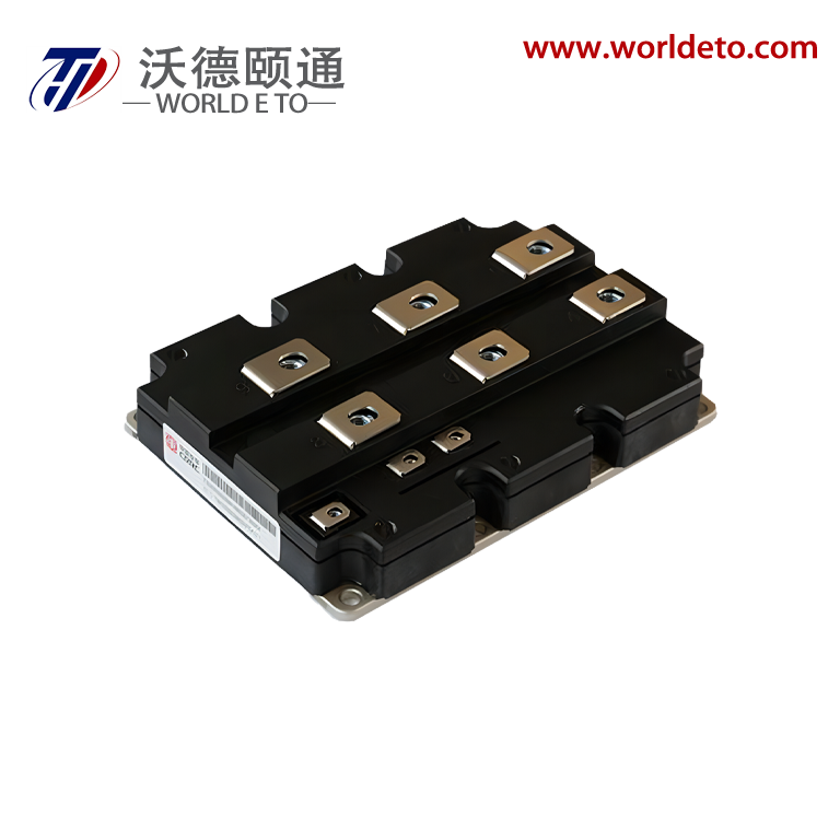
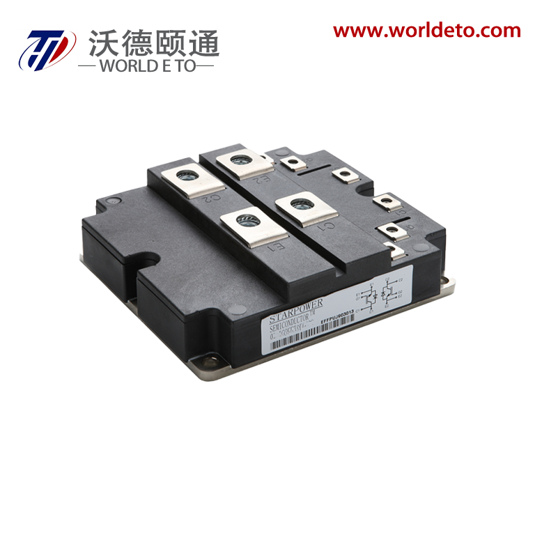
Brief introduction:
High voltage, single switch IGBT modules produced by CRRC. 3300V 1200A.
Features
- SPT+chip-set for ultra low switching losses
- Low VCE sat
- Low driving power
- AlSiC base plate for high power cycling capability
- AlN substrate for low thermal resistance
Typical application
- Traction rives
- DC Chopper
- Medium voltage inverters/converters
- Medium voltage UPS system
- Wind power system
Maximum rated values
Parameter |
Symbol |
Conditions |
Min |
Max |
Unit |
Collector-emitter voltage |
VCES |
VGE=0V,Tvj≥25°C |
|
3300 |
V |
DC collector current |
IC |
TC =80 °C |
|
1200 |
A |
Peak collector current |
ICM |
tp =1ms,Tc=80°C |
|
2400 |
A |
Gate emitter voltage |
VGE |
|
-20 |
20 |
V |
Total power dissipation |
Ptot |
TC =25°C, per switch(IGBT) |
|
10500 |
W |
DC forward current |
IF |
|
|
1200 |
A |
Peak forward current |
IFRM |
tp = 1 ms |
|
2400 |
A |
Surge current |
IFSM |
VR = 0 V, Tvj = 125 °C,
tp = 10 ms, half-sinewave
|
|
9000 |
A |
IGBT short circuit SOA |
tpsc |
VCC = 2500 V, VCEM CHIP ≤ 3300V VGE ≤ 15 V, Tvj ≤ 125 °C |
|
10 |
µs |
Isolation voltage |
Visol |
1 min, f = 50 Hz |
|
10200 |
V |
Junction temperature |
Tvj |
|
|
150 |
°C |
Junction operating temperature |
Tvj(op) |
|
-50 |
125 |
°C |
Case temperature |
TC |
|
-50 |
125 |
°C |
Storage temperature |
Tstg |
|
-50 |
125 |
°C |
|
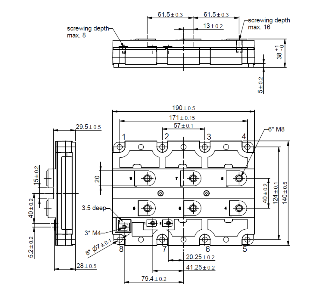
Mounting torques
|
M s |
Base-heatsink, M6 screws |
4 |
6 |
Nm
|
Mt1 |
Main terminals, M8 screws , |
8 |
10 |
Mt2 |
Auxiliary terminals, M6 screws |
2 |
3 |
IGBT characteristic
Parameter |
Symbol |
Conditions |
min |
typ |
max |
Unit |
Collector (- emitter) breakdown voltage |
V(BR)CES |
VGE = 0 V, IC= 12 mA, Tvj = 25 °C
|
3300 |
|
|
V
|
Collector emitter saturation voltage |
VCE sat
|
C = 1200 A, VGE= 15 V
|
Tvj=25°C |
|
3.1 |
3.4 |
V |
Tvj=125°C |
|
3.8 |
4.3 |
V |
Collector cut off current |
ICES |
VCE = 3300 V, VGE = 0 V
|
Tvj=25°C |
|
|
12 |
mA |
Tvj=125°C |
|
|
120 |
mA |
Gate leakage current |
IGES |
VCE = 0 V, VGE = ± 20 V, Tvj =125 °C
|
-500 |
|
500 |
nA
|
Gate-emitter threshold voltage |
VGE(th) |
IC =240mA,VCE =VGE,Tvj =25°C |
5.5 |
|
7.5 |
V |
Gate charge |
Qg |
IC =1200 A VCE =1800V VGE = -15V ..15 V |
|
12.1 |
|
µC |
Input capacitance |
Cies |
VCE = 25 V, V GE = 0 V, f = 1 MHz, Tvj = 25 °C
|
|
187 |
|
nF |
Output capacitance |
Coes |
|
11.57 |
|
nF |
Reverse transfer capacitance |
Cres |
|
2.22 |
|
nF |
Turn-on delay time |
td(on)
|
VCC = 1800 V, IC = 1200A,
RG = 3.9Ω ,VGE =±15V
L σ = 280nH, inductive load
|
Tvj=25°C |
|
750 |
|
ns |
Tvj=125°C |
|
750 |
|
ns |
Rise time |
tr |
Tvj=25°C |
|
400 |
|
ns |
Tvj=125°C |
|
470 |
|
ns |
Turn-off delay time |
td(off) |
Tvj=25°C |
|
1600 |
|
ns |
Tvj=125°C |
|
1800 |
|
ns |
Fall time |
tf |
Tvj=25°C |
|
1100 |
|
ns |
Tvj=125°C |
|
1200 |
|
ns |
Turn -on switching loss |
Eon
|
Tvj=25°C |
|
1400 |
|
mJ |
Tvj=125°C |
|
1800 |
|
mJ |
Turn-off switching loss energy |
Eoff
|
Tvj=25°C |
|
1300 |
|
mJ |
Tvj=125°C |
|
1700 |
|
mJ |
Short circuit current |
ISC
|
VCC = 2500 V, VGE = 15V, L σ = 280nH, inductive load |
|
5000
|
|
A
|
Diode characteristic
Parameter |
Symbol |
Conditions |
min |
typ |
max |
Unit |
Forward voltage |
VF
|
IF = 1200 A |
Tvj = 25 °C |
|
2.3 |
2.6 |
V |
Tvj = 125 °C |
|
2.35 |
2.6 |
V |
Reverse recovery current |
Irr
|
VCC= 1800 V, IC= 1200 A,
RG=2.3Ω ,VGE=±15V, L σ = 280nH,inductive load
|
Tvj = 25 °C |
|
900 |
|
A |
Tvj = 125 °C |
|
1000 |
|
A |
Recovered charge |
Qrr
|
Tvj = 25 °C |
|
700 |
|
µC |
Tvj = 125 °C |
|
1000 |
|
µC |
Reverse recovery time |
trr
|
Tvj = 25 °C |
|
850 |
|
ns |
Tvj = 125 °C |
|
2200 |
|
ns |
Reverse recovery energy |
Erec
|
Tvj = 25 °C |
|
850 |
|
mJ |
Tvj = 125 °C |
|
1300 |
|
mJ |