
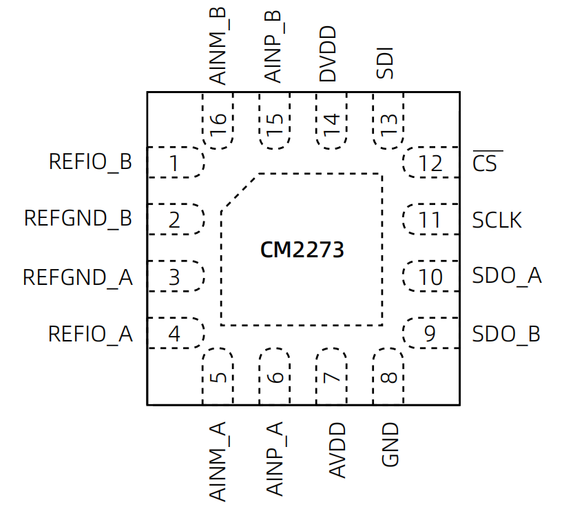
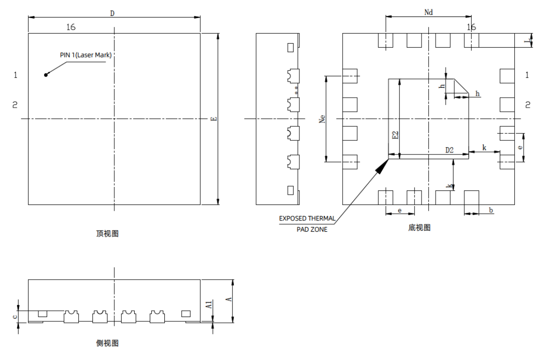
Pin configuration
| Mark | Dimensions (mm) | |||||||||||||||||||||||
| Min | Typ | Max | ||||||||||||||||||||||
| A | 0.70 | 0.75 | 0.80 | |||||||||||||||||||||
| A1 | 0 | 0.02 | 0.05 | |||||||||||||||||||||
| b | 0.20 | 0.25 | 0.30 | |||||||||||||||||||||
| c | 0.20 (REF) | |||||||||||||||||||||||
| D | 2.90 | 3.00 | 3.10 | |||||||||||||||||||||
| D2 | 1.30 | 1.40 | 1.50 | |||||||||||||||||||||
| e | 0.50 (BSC) | |||||||||||||||||||||||
| E | 2.90 | 3.00 | 3.10 | |||||||||||||||||||||
| E2 | 1.30 | 1.40 | 1.50 | |||||||||||||||||||||
| Nd | 1.50 (BSC) | |||||||||||||||||||||||
| Ne | 1.50 (BSC) | |||||||||||||||||||||||
| L | 0.20 | 0.25 | 0.30 | |||||||||||||||||||||
| h | 0.20 | 0.25 | 0.30 | |||||||||||||||||||||
| k | 0.55 (REF) | |||||||||||||||||||||||
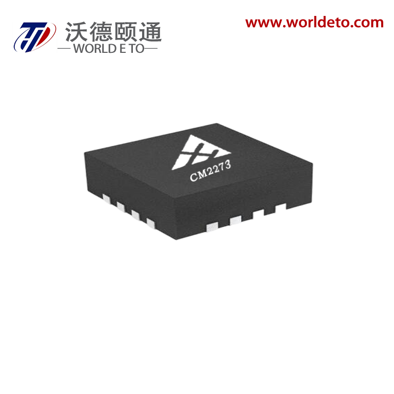
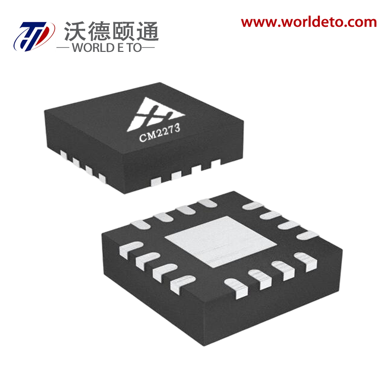
Appearance structure
Application Case:Power Quality Measurement Using CM2273

Objective:
To use the CM2273 ADC for power quality monitoring by measuring parameters such as voltage, current, and frequency. The ADC will help convert analog signals from power system sensors into digital data for analysis and monitoring.
1. System Components:
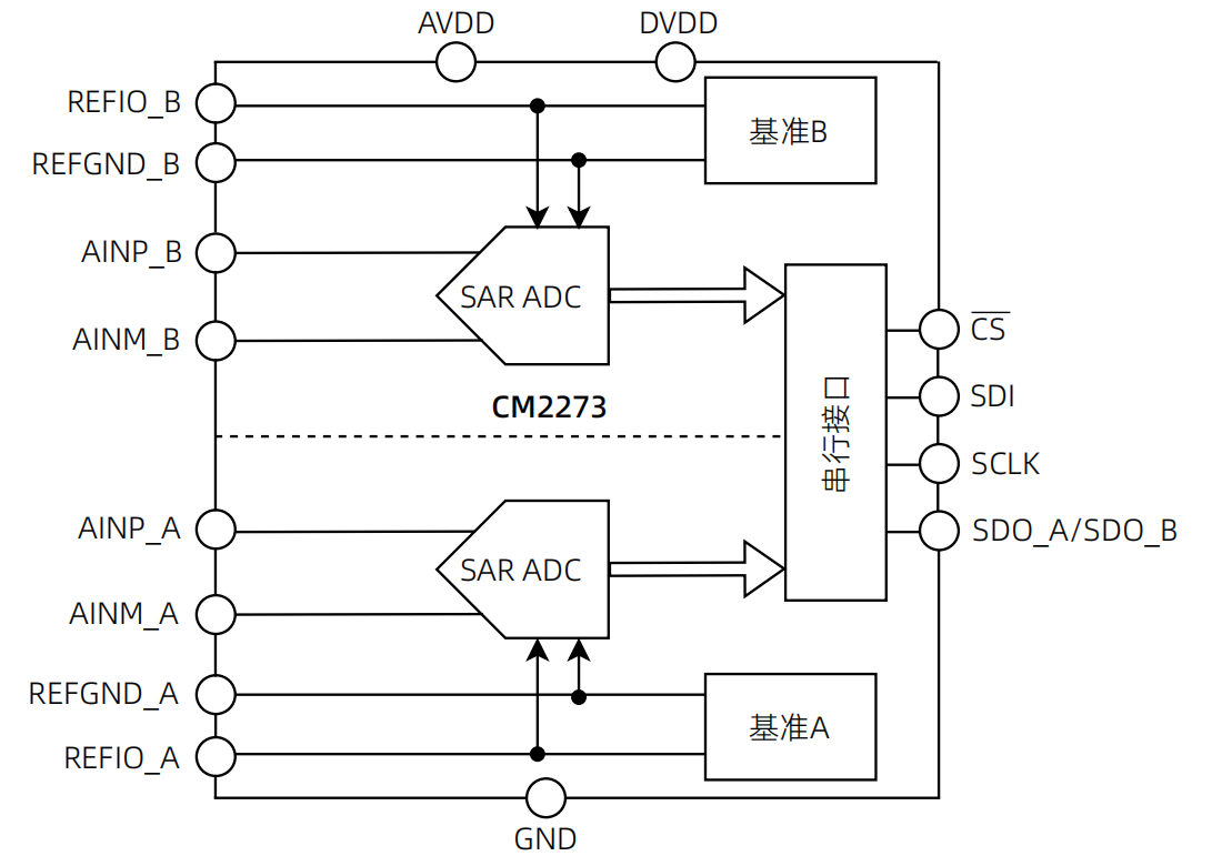
CM2273: A 16-bit SAR ADC with high-speed sampling capability, used to digitize the analog signals from power quality sensors.
Voltage Sensor: Measures the voltage waveform of the power system (e.g., from the electrical grid).
Current Sensor: Measures the current waveform passing through the power system.
Power Analyzer/Controller: A microcontroller or digital signal processor (DSP) that collects data from the CM2273, processes the measurements, and calculates key power quality parameters (e.g., voltage, current, power factor).
Software: Power quality monitoring software that processes the collected data, performs real-time analysis, and provides reports on the power quality.
2. Power Quality Parameters to Measure:
Voltage: Measuring RMS voltage to ensure that it stays within the required range.
Current: Measuring RMS current to evaluate the load and determine any imbalances.
Frequency: Measuring the frequency of the power supply to ensure it stays at nominal levels (50 Hz or 60 Hz).
Harmonics: Measuring harmonic distortion in voltage and current waveforms to evaluate any non-linear behavior in the power system.
Power Factor: Calculating the ratio of real power to apparent power to evaluate the efficiency of the system.
3. System Configuration and Measurement Setup:
3.1 Voltage Measurement:
Use a voltage sensor (e.g., a voltage divider or a differential probe) to measure the AC voltage from the power system.
The voltage signal will be fed into theCM2273's differential input channels.
The CM2273 will sample the voltage waveform, converting it into a digital signal for further analysis.
3.2 Current Measurement:
Use acurrent sensor(e.g., a Hall-effect current sensor or a current transformer) to measure the current flowing through the system.
Similar to the voltage measurement, the current signal is input into the CM2273 to be digitized.
3.3 Frequency Measurement:
The frequency can be measured by analyzing the time interval between zero-crossings or using a frequency counter.
Alternatively, the CM2273 can sample the voltage waveform, and the controller can analyze the frequency by detecting peaks in the signal.
4. Data Acquisition and Signal Processing:
The CM2273 continuously samples the voltage and current waveforms at a predefined sampling rate (typically 10 kSPS or higher, depending on the application).
The CM2273 outputs digital data to the microcontroller, which then processes the signals to calculate key parameters such as:
RMS Voltage: The square root of the average of the squared voltage values.
RMS Current: The square root of the average of the squared current values.
Power Factor: Using the phase difference between the voltage and current waveforms.
Harmonic Distortion: Performing a Fourier Transform to analyze the harmonic content in the voltage and current waveforms.
Frequency: Determining the frequency by analyzing the waveform cycle.
5. Power Quality Analysis:
The microcontroller or DSP will analyze the acquired data and compare it against power quality standards (e.g., IEEE 519 for harmonic distortion, IEC 61000 for electromagnetic compatibility).
The system can trigger alarms or notifications if power quality parameters fall outside acceptable limits.
6. Performance Optimization:
Sampling Rate: Ensure that the CM2273’s sampling rate is high enough to accurately capture the voltage and current waveforms, especially when measuring high-frequency harmonics.
Filter: Implement digital filters (low-pass, band-pass) in the software to remove noise or unwanted high-frequency components from the signals.
Calibration**: Regularly calibrate the sensors and the CM2273 to maintain measurement accuracy over time.
7. Example Circuit Design:
Voltage and Current Sensors to CM2273: Connect the outputs of the voltage and current sensors to the differential input channels of the CM2273.
CM2273 to Controller**: Use the SPI or I2C interface to send the digital data from the CM2273 to the microcontroller or DSP for processing.
Microcontroller to Power Quality Software: The processed data is sent to a power quality monitoring software running on a PC or embedde