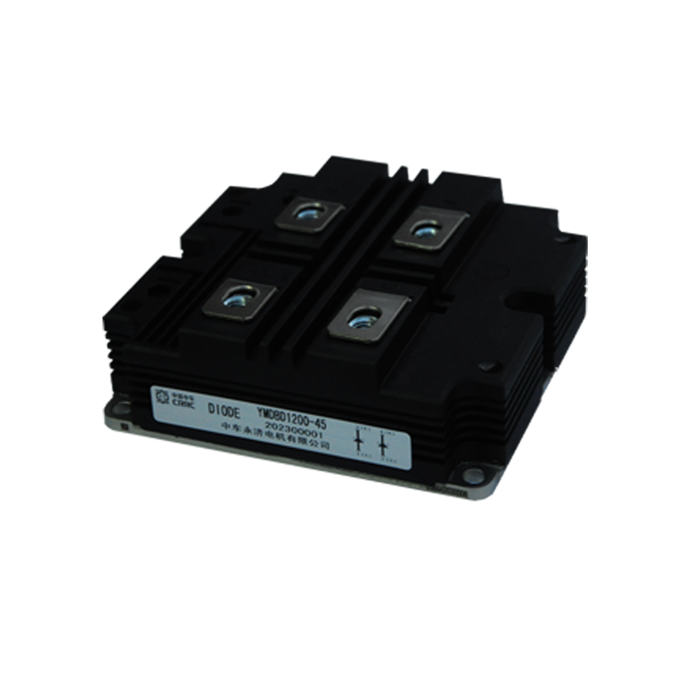
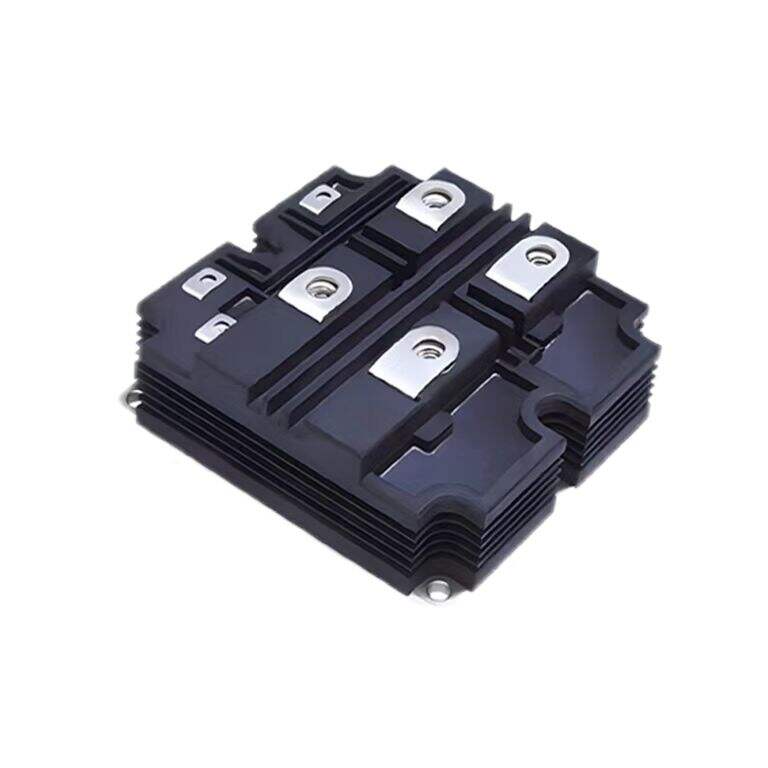
استراتيجيات أساسية لحماية وحدات الدايود في الإلكترونيات الحديثة
الحماية. ومع تطور الإلكترونيات الكهربائية بشكل متزايد، أصبحت حماية وحدات الدايود من زيادة التيار والارتفاعات الجهدية عاملاً أساسيًا يأخذه المهندسون والفنيون بعين الاعتبار. وحدة الديود فهم وتنفيذ تدابير حماية فعالة لا يطيل عمر المكونات فحسب، بل يضمن أيضًا تشغيل مستقر للنظام ويمنع الأعطال المكلفة.
تواجه الأنظمة الإلكترونية الحديثة العديد من التحديات الناتجة عن تقلبات الطاقة والانomalies الكهربائية. بدون حماية كافية لمODULEات الدايود، يمكن أن تتعرض هذه المكونات الحيوية للفشل الكارثي، مما يؤدي إلى توقف النظام وإجراء إصلاحات مكلفة. يستعرض هذا الدليل الشامل استراتيجيات مثبتة وممارسات أفضل لحماية MODULEات الدايود ضد التهديدات الكهربائية الشائعة.

فهم ضعفاء MODULE الدايود
الأسباب الشائعة لفشل MODULE الدايود
عادةً ما تفشل MODULEات الدايود بسبب عدة عوامل رئيسية، ومن بينها يُعد تيار الزائد وارتفاعات الجهد السبب الأكثر شيوعًا. يمكن أن تسبب الإجهادات الحرارية الناتجة عن تدفق تيار مفرط تلفًا فوريًا أو تدهورًا تدريجيًا بمرور الوقت. قد تؤدي ارتفاعات الجهد، التي تنتج غالبًا عن عمليات التبديل أو ضربات البرق، إلى تجاوز سعة MODULE خلال جزء من الثانية، مما يؤدي إلى الفشل الفوري.
تلعب الظروف البيئية أيضًا دورًا مهمًا في هشاشة وحدة الدايود. يمكن أن تؤدي التقلبات في درجة الحرارة والرطوبة والاهتزاز إلى تفاقم تأثيرات الإجهاد الكهربائي، مما يجعل الحماية المناسبة أكثر أهمية. وفهم آليات الفشل هذه هي الخطوة الأولى نحو تنفيذ استراتيجيات حماية فعالة.
تأثير الإجهاد الكهربائي على أداء الوحدة
يظهر الإجهاد الكهربائي بعدة طرق، ويؤثر على الأداء الفوري وموثوقية الوحدات الدايودية على المدى الطويل. عندما تتعرض الوحدات لظروف تيار زائد، فإنها تواجه زيادة في إنتاج الحرارة، مما قد يُضعف سلامة الوصلة ويؤدي إلى انهيار حراري. ويمكن أن تؤدي القفزات الجهدية إلى انهيار انهياري، ما قد يسبب أضرارًا دائمة للبنية شبه الموصلة.
يمكن للتعرض المنتظم حتى للإجهادات الكهربائية البسيطة أن يؤدي إلى أضرار تراكمية، مما يُسهم تدريجيًا في تدهور خصائص أداء الوحدة. غالبًا ما يتجلى هذا التدهور في شكل زيادة تيار التسرب، وارتفاع في انخفاض الجهد الأمامي، وانخفاض في قدرة التعامل مع التيار.
تطبيق حلول حماية من زيادة التيار
تركيب مصهر سريع الاستجابة
تُعد المصاهر السريعة الاستجابة هي الخط الأول من الدفاع ضد حالات زيادة التيار. يتطلب اختيار تصنيف المصهر المناسب مراعاة دقيقة لمعايير تشغيل الوحدة وسيناريوهات الأعطال المحتملة. يجب أن يستجيب المصهر بسرعة كافية لمنع الأضرار، مع تجنب الانقطاع غير الضروري أثناء التشغيل العادي.
موقع التركيب وتنسيق المصاهر هما عنصران أساسيان في حماية فعالة من زيادة التيار. يضمن التوضع المناسب مستوى حماية مثاليًا مع الحفاظ على سهولة الوصول إلى النظام للصيانة. قد تكون هناك حاجة إلى تكوينات متعددة من المصاهر في الأنظمة المعقدة التي تتضمن متطلبات تيار متفاوتة.
دوائر الحد من التيار الإلكتروني
توفر الدوائر الإلكترونية المتطورة لتحديد التيار حماية متقدمة مع الحفاظ على وظائف النظام. تقوم هذه الدوائر بمراقبة تدفق التيار في الوقت الفعلي ويمكنها الاستجابة لظروف التيار الزائد خلال ميكروثانية. وعلى عكس المزمنات، يمكن للمحددات الإلكترونية أن تعيد التشغيل تلقائيًا بمجرد زوال حالة العطل.
تشمل الاعتبارات التصميمية لدوائر الحد من التيار الزمن المستغرق للرد، وهبوط الجهد، واستهلاك الطاقة. وتمكن عملية الدمج مع أنظمة التحكم الحالية من وضع استراتيجيات حماية منسقة وتعزيز قدرات المراقبة.
تدابير حماية ضد زيادة الجهد
أجهزة كبت الجهد العابر
تُعتبر أجهزة كبت الجهد العابر (TVS) مكونات أساسية لحماية وحدات الدايود ضد زيادات الجهد. تستجيب هذه الأجهزة فورًا لظروف الجهد الزائد، وتحدد الجهد عند مستويات آمنة قبل حدوث أي ضرر. تشمل معايير الاختيار الجهد الانهياري، وقدرة الكبت، وزمن الاستجابة.
يتطلب تنفيذ أجهزة TVS اهتمامًا دقيقًا بتصميم التخطيط وإدارة الحرارة. يقلل التوضع الصحيح للأجهزة من الحث الزائد المتوازي مع ضمان تبديد كافٍ للحرارة أثناء حالات التيار المفاجئ. قد تكون هناك حاجة إلى مراحل حماية متعددة في البيئات القاسية.
شبكات مثبط RC
توفر شبكات مثبط RC حماية إضافية ضد زيادة الجهد بينما تساعد أيضًا في تشكيل موجات التشغيل. تمتص هذه الشبكات السلبية الطاقة الناتجة عن التقلبات الجهد وتقلل من تأثيرات التردد الزائد. إن اختيار المكونات المناسبة ووضعها بدقة يشكلان أمرًا بالغ الأهمية لتحقيق أداء مثالي.
تشمل الاعتبارات التصميمية استهلاك الطاقة، تصنيف الجهد، والاستجابة الترددية. إن الدمج مع إجراءات حماية أخرى يضمن حماية شاملة ضد زيادة الجهد مع الحفاظ على كفاءة النظام.
استراتيجيات إدارة الحرارة
تصميم مبردات الحرارة واختيارها
إن الإدارة الفعالة للحرارة ضرورية للحفاظ على موثوقية وحدة الدايود. يجب أن تراعي عملية اختيار مشتت الحرارة أقصى قدرة على التبديد الحراري، ودرجة الحرارة المحيطة، والمساحة المتاحة. وتساعد مواد الواجهة الحرارية المناسبة في نقل الحرارة بكفاءة من الوحدة إلى مشتت الحرارة.
تتضمن تصميمات مشتتات الحرارة المتقدمة ميزات مثل التبريد بالهواء المُجبر والمواد قابلة للتغير الطوري لتحسين الأداء الحراري. ويُعد المراقبة الدورية للظروف الحرارية أمرًا مفيدًا في منع الفشل الناتج عن ارتفاع درجة الحرارة وضمان تشغيل نظام الحماية بشكل مثالي.
تكامل نظام التبريد
يتطلب دمج أنظمة التبريد مع إجراءات الحماية تنسيقًا دقيقًا بين المكونات المتعددة. يجب أن تكون حلول التبريد النشطة مثل المراوح أو أنظمة التبريد السائلية ذات الأحجام المناسبة وأنظمة التحكم الفعالة للحفاظ على درجات حرارة تشغيل آمنة تحت جميع الظروف.
تلعب أنظمة المراقبة والتحكم دوراً أساسياً في الحفاظ على الظروف الحرارية المثلى. تسمح أجهزة استشعار درجة الحرارة والدوائر التغذوية بتعديل ديناميكي لمعايير التبريد بناءً على الظروف التشغيلية الفعلية.
بروتوكولات المراقبة والصيانة
تنفيذ أنظمة التشخيص
تساعد المراقبة الدورية لأداء وحدة الدايود في تحديد المشكلات المحتملة قبل أن تصبح حرجة. يجب أن تقوم أنظمة التشخيص بتتبع المعايير الرئيسية بما في ذلك التيار والجهد ودرجة الحرارة. قد تشمل حلول المراقبة المتقدمة إمكانات الصيانة التنبؤية استناداً إلى تحليل الاتجاهات.
تمكن جمع البيانات وتحليلها من التخطيط للصيانة بشكل استباقي وتحسين النظام. وتوفر الإدماج مع أنظمة إدارة المرافق رقابة شاملة وإنذاراً مبكراً لمشكلات ناشئة.
جداول صيانة وقائية
يُضمن إنشاء جداول صيانة منتظمة استمرارية فعالية تدابير الحماية. يجب أن تشمل بروتوكولات الفحص الفحص البصري واختبارات الكهرباء والتصوير الحراري. وتساعد وثائق أنشطة الصيانة في تتبع حالة النظام وتحديد المشكلات المتكررة.
تدريب أفراد الصيانة على إجراءات الفحص والاختبار الصحيحة ضروري لضمان صيانة وقائية فعالة. كما يضمن المراجعة الدورية وتحديث بروتوكولات الصيانة التزامها بالمتطلبات المتغيرة للنظام.
الأسئلة الشائعة
ما هي أكثر المعايير أهميةً التي يجب مراقبتها لحماية وحدة الدايود؟
تشمل المعايير الأكثر أهمية تدفق التيار ومستويات الجهد ودرجة حرارة التشغيل وأداء نظام التبريد. تساعد المراقبة المنتظمة لهذه المعايير في منع الأعطال وضمان تشغيل النظام الأمثل. قد تُراقب الأنظمة المتقدمة أيضًا خصائص التبديل وحالة أجهزة الحماية.
ما مدى تكرار فحص نظم الحماية واختبارها؟
يجب أن تخضع أنظمة الحماية لفحص واختبار شامل على الأقل كل ثلاثة أشهر، مع إجراء فحوصات أكثر تكرارًا في البيئات القاسية أو التطبيقات الحرجة. يجب إجراء الفحوصات البصرية شهريًا، في حين يمكن إجراء التصوير الحراري واختبارات الكهرباء كل ثلاثة أشهر أو نصف سنويًا حسب متطلبات النظام.
ما هي علامات فشل وشيك في وحدة الدايود؟
تشمل العلامات الشائعة ارتفاع درجة حرارة التشغيل، وتغيرات في انخفاض الجهد الأمامي، والضوضاء أو الاهتزاز غير المعتاد، والأضرار المادية المرئية. يمكن أن يكشف المراقبة المنتظمة عن التغيرات الدقيقة في الأداء التي قد تشير إلى مشاكل ناشئة. تساعد المراجعة الفورية لأي ظروف غير طبيعية في منع الفشل الكارثي.

